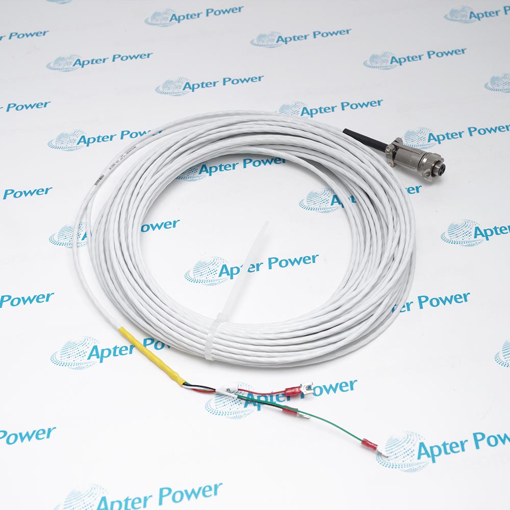
The 130539-45 is a Bently Nevada 45 ft accelerometer interconnect cable made with three-conductor shielded 18 AWG cable. It has a three-socket plug with a fluorosilicone elastomer boot at one end and terminal lugs at the other.
- Accelerometer interconnect cable
- 45 ft (approximately 13.7 m)
- 3 conductor
- 18 AWG (1.0 mm²)
It connects a compatible Bently Nevada acceleration transducer to terminal-based field wiring or monitoring equipment, carrying the sensor connection while the molded boot protects the plug end from splash and environmental exposure. For dependable measurement, follow the official system-matching, target, mounting, cabling, environmental, and approval instructions.
Important Notice: The manufacturer identifies 130539 as a length-coded cable. Confirm the compatible sensor connector and follow manual 133080-01 before installation.
Apter Power 130539-45 Original Product Manual
Important Notice: This Apter Power original manual summarizes manufacturer-published technical data for the exact ordering code. Verify the physical nameplate and current manufacturer installation documents before use.
Gearbox Acceleration MonitoringConnects compatible high-frequency accelerometers used on industrial gearboxes.
330400 AccelerometerProvides the published booted interconnect-cable option for 330400 acceleration transducers.
330425 AccelerometerConnects the 330425 accelerometer to terminal-based field wiring and monitoring equipment.
330450 HTAS InterconnectionThe 330450 High Temperature Acceleration System datasheet lists 130539 as an interconnect-cable option.
Machine-to-Panel WiringRoutes a shielded sensor connection across a 45 ft installation distance.
Splash-Exposed Sensor ConnectionsThe fluorosilicone boot protects the three-socket plug end in compatible installations.
Read and follow Bently Nevada 330400 and 330425 Accelerometer Acceleration Transducers Datasheet 141638 Rev. AB and the applicable installation instructions before use. Verify the complete ordering code from the physical nameplate and match every component to the published system configuration.
1Follow installation manual 133080-01 referenced by the manufacturer for this cable construction.
2Confirm the three-socket plug matches the exact accelerometer before routing the cable.
3Maintain shield continuity and terminate the field-end lugs according to the sensor and monitor wiring drawings.
4Provide strain relief and protect the 45 ft cable from abrasion, sharp bends, and hot surfaces outside the compatible sensor limits.
5Do not infer hazardous-area approval from the cable part number; approval depends on the complete installed sensor system.


 Videos
 News
News Applications