Speak to a sourcing specialist
sales13@apterpower.com

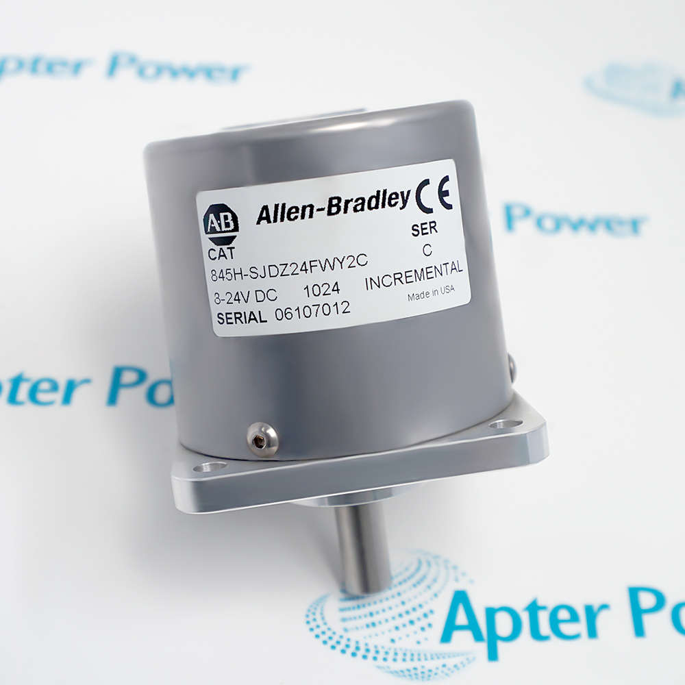
845H-SJDZ24FWY2C

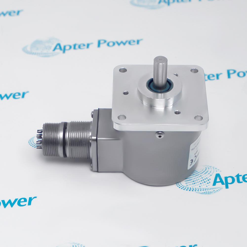
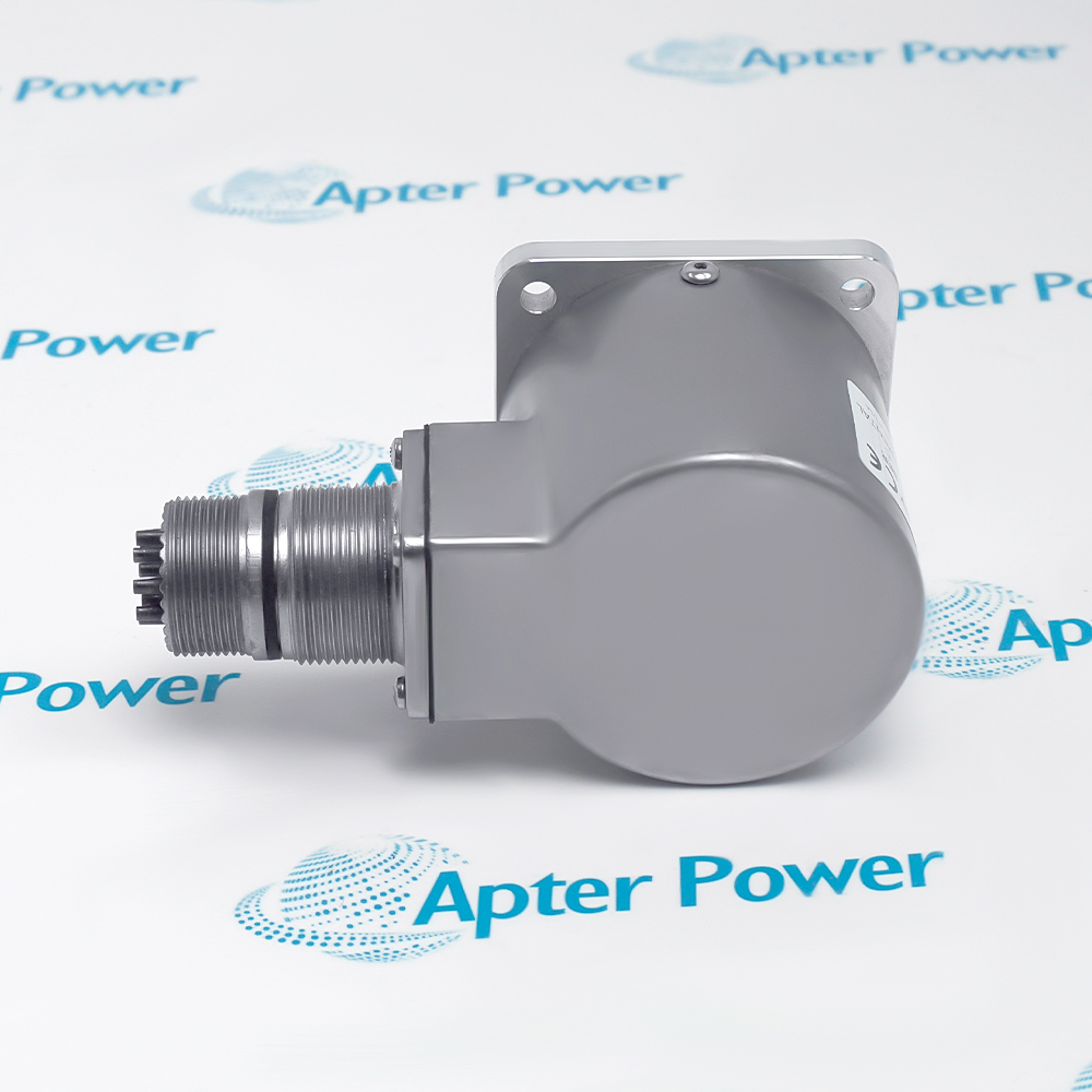
Size 25 Incremental Optical Encoder
Allen-Bradley 845H-SJDZ24FWY2C (1)
Allen-Bradley 845H-SJDZ24FWY2C (2)
Allen-Bradley 845H-SJDZ24FWY2C (3)
Allen-Bradley 845H-SJDZ24FWY2C (1)
Allen-Bradley 845H-SJDZ24FWY2C (2)
Allen-Bradley 845H-SJDZ24FWY2C (3)
Product image is representative; revision or series may vary. Contact us to request a specific version.

Product Describe:

Allen-Bradley 845H-SJDZ24FWY2C Size 25 Incremental Optical Encoder
  • Manufacturer part number
    845H-SJDZ24FWY2C
  • Shipping
    Swift global dispatch
  • Condition
    New, original product
  • Shipping size (est.)
    12.2cm x 6.7cm x 9.5cm
  • Country of Origin
    USA
Get a quick price for 845H-SJDZ24FWY2C
E-mail *
Mobile
Company
Content *
Quantity *
Upload (gif, jpg, jpeg, png, bmp, doc, docx, xls, xlsx, ppt, pdf, csv)
For more information on how your data is processed and stored by Apterpower please read our privacy policy

What happens after you enquire

  • 0

    Share the complete 845H-SJDZ24FWY2C marking

    Send clear photographs of the full encoder label, shaft, flange and radial connector. Include the installed counter and coupling reference so the exact offered configuration can be checked.

  • 1

    Review the encoder interface

    Our team compares the selected 8–24 V DC supply, 5 V differential receiver, 1024-PPR count and mating-connector option with the installed drawing.

  • 2

    Confirm the offered unit and dispatch

    Receive photographs of the actual 845H-SJDZ24FWY2C, its included connector, condition, quantity and current dispatch arrangement with the quotation.

  • Match the complete marking

    Keep 845H-SJDZ24FWY2C intact, including the shaft, supply, output, resolution and connector suffixes. Compare the label and mounting with the installed encoder drawing.

  • Check the offered item before ordering

    Request available label and connector photos. Have your maintenance team compare the offered 845H-SJDZ24FWY2C with the installed coupling, controller receiver and applicable Rockwell documentation.

Technical specifications for 845H-SJDZ24FWY2C

  • Manufacturer:
    Allen-Bradley
  • Product Category:
    General Automation
  • Spare Part Number:
    845H-SJDZ24FWY2C
  • Weight:
    0.48 kg
  • Tariff Code:
    8537101190
  • Encoder family:
    Bulletin 845H, size 25 high performance
  • Code format:
    Incremental A/B quadrature plus zero index
  • Mounting option D:
    Square flange
  • Shaft option Z:
    Smooth 3/8 in. diameter
  • Supply option 2:
    8–24 V DC, unregulated
  • Output option 4:
    5 V DC differential line driver, RS-422
  • Resolution option FW:
    1024 pulses per revolution
  • Connection option Y2:
    Radial side connector
  • Connection suffix C:
    Mating connector included
  • Encoder connector:
    10-pin for differential line-driver output
  • A/B phase relation:
    90° ±22° electrical; A leads B counterclockwise, family data
  • Zero-index pulse:
    Half cycle gated to channel B, family data
  • Maximum data response:
    210 kHz, family data
  • Maximum index response:
    125 kHz, family data
  • Mechanical speed ceiling:
    6000 rpm, family data
  • Enclosure protection:
    NEMA Type 4 and 13; IP66, family data
  • Operating temperature:
    0 to +60 °C, family data
  • Storage temperature:
    −25 to +90 °C, family data

Information

Overview Downloads Applications / Compatibility Product Precautions
  • This 845H configuration pairs a square-flange, smooth 3/8 in. shaft with a 1024-pulse incremental output and a radial mating connector; the connected counter must be configured for its 5 V differential signals.
Counter configuration: Use 1024 PPR and the selected x1/x2/x4 decoding mode to establish counts per revolution.
Signal pairing: Land A/Ā, B/B̄ and Z/Z̄ as differential pairs; preserve the correct 5 V receiver interface.
Mechanical alignment: Use a suitable coupling and verify flange and shaft alignment before applying speed.
The complete 845H-SJDZ24FWY2C order code selects a square-flange size 25 encoder with a smooth 3/8 in. shaft and 1024 pulses per revolution. The FW code describes the incremental code disk; the A/B channel interpretation depends on the counter decoding mode, so pulses per revolution must not be confused with counted edges.

The encoder is supplied from 8–24 V DC but its selected output option is a 5 V differential RS-422 line driver. The 10-pin radial connector carries A/Ā, B/B̄ and zero-index Z/Z̄ paths along with supply, return and case grounding. The C suffix identifies the mating connector option; inspect the offered connector and cable before replacing the installed unit.

Rockwell specifies a maximum 210 kHz data response and 6000 rpm mechanical ceiling for this family. At 1024 PPR, the mechanical ceiling is the binding speed limit under the stated response values. Fit a suitable flexible coupling, preserve shield and grounding arrangements and prove direction, index and counted speed against a known reference during commissioning.
Controller platform reference: Bulletin 845H incremental feedback. Match the installed counter input, shaft coupling and connector to the complete order code.
Technical downloads for Allen-Bradley 845H-SJDZ24FWY2C: model-specific technical reference and installation review.
Use the manufacturer source identified in each document to confirm applicability to the installed configuration.
Prepare Allen-Bradley 845H-SJDZ24FWY2C using the approved machine documentation and site procedure.
Power-output distinction

Check 8–24 V encoder supply and 5 V RS-422 receiver compatibility as separate requirements.

Connector identity

Verify the radial 10-pin interface and supplied mating connector against the installed cable.

Shaft coupling

Avoid rigid shaft coupling; inspect offset, axial load and flange alignment.

Pulse scaling

Set 1024 PPR and the actual x1/x2/x4 counter mode before validating displayed speed.

Shield routing

Keep paired signal conductors and the approved shield bond away from high-noise power wiring.

Acceptance test

Rotate in a controlled direction and prove A/B order, zero index and speed at the controller.

Alternative Names

845H-SJDZ24FWY2C Allen-Bradley 845H-SJDZ24FWY2C Bulletin 845H 845H-SJDZ24FWY2C

Technical notes

Order-code relationship: D/Z/2/4/FW/Y2/C selects square flange, 3/8 in. shaft, 8–24 V DC supply, 5 V differential output, 1024 PPR, radial connector and mating connector.

System interpretation: The receiver decoding factor determines displayed counts per revolution; validate it against a known shaft turn.

Technical reference: Rockwell Automation C116 Sensor Catalog, Bulletin 845H; 1746-IN011C-EN-P provides an example high-speed counter connection.


FAQ View All FAQ

  • How should 845H-SJDZ24FWY2C counts per revolution be configured in a quadrature counter?
    Start with 1024 pulses per revolution from the FW order code. A counter using x1, x2 or x4 decoding may accumulate 1024, 2048 or 4096 edges per shaft turn; select the mode used by the installed control program and prove it with one known revolution.
  • Why can 845H-SJDZ24FWY2C be powered correctly yet produce unusable counter signals?
    The encoder supply is 8–24 V DC while code 4 delivers 5 V RS-422 differential outputs. Verify the receiver input type, A/Ā and B/B̄ polarity, cable continuity and ground reference rather than assuming supply and signal voltage are identical.
  • How is direction reversal diagnosed on 845H-SJDZ24FWY2C?
    Check the A/B phase order against a known shaft direction; the family reference states that A leads B for counterclockwise rotation. Compare wiring polarity and the controller direction convention before changing software scaling.
  • How should the index signal of 845H-SJDZ24FWY2C be proved?
    Observe the differential Z/Z̄ pair during a slow controlled turn and confirm one valid gated reference event per revolution. Compare the controller capture point with the machine home sequence and check the index receiver wiring.
  • What limits the usable shaft speed of 845H-SJDZ24FWY2C?
    For this 1024-PPR selection, compare the family 210 kHz data response with the 6000 rpm mechanical ceiling. The 1024-PPR pulse frequency at 6000 rpm is 102.4 kHz, so the mechanical limit is lower under these stated conditions; also respect the coupling and shaft-load limits.
  • What connector inspection matters before replacing 845H-SJDZ24FWY2C?
    Confirm the radial 10-pin differential connector, the C-suffix mating connector and the pin assignments in the applicable Rockwell drawing. Compare shell, keying, cable exit and strain relief with the installed harness before energizing.
  • What can cause intermittent pulses from 845H-SJDZ24FWY2C during vibration?
    Inspect the flexible coupling, shaft runout, connector retention, shield bond and A/B pair continuity while observing the counter diagnostics. Correlate dropouts with speed and machine vibration before assigning the fault to the encoder.
  • How should 845H-SJDZ24FWY2C be accepted after installation?
    Record the complete marking, supply at the encoder, receiver wiring, controller decoding mode and count over a known revolution. Prove direction, zero-index capture and speed across the approved operating range in the machine acceptance state.
SPEAK TO OUR TEAM
Let’s find the right solution for you.
Send us the part number, quantity and delivery destination. Our team will help confirm availability and lead time.
  • Whatsapp: +86 18030235313

    Send us a message.
  • sales13@apterpower.com

    Complete our online form.
  • +86 18030235313

    Speak to our team in your native language.