-
Match the complete marking
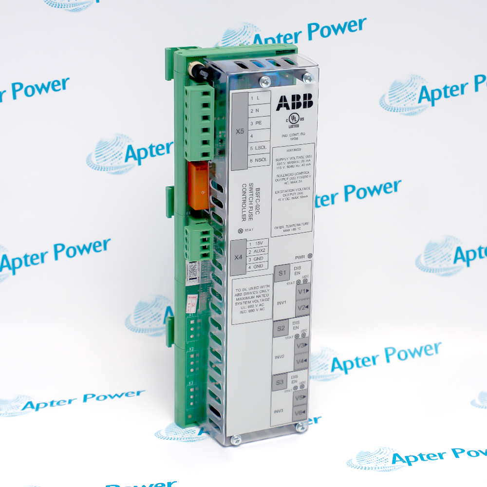
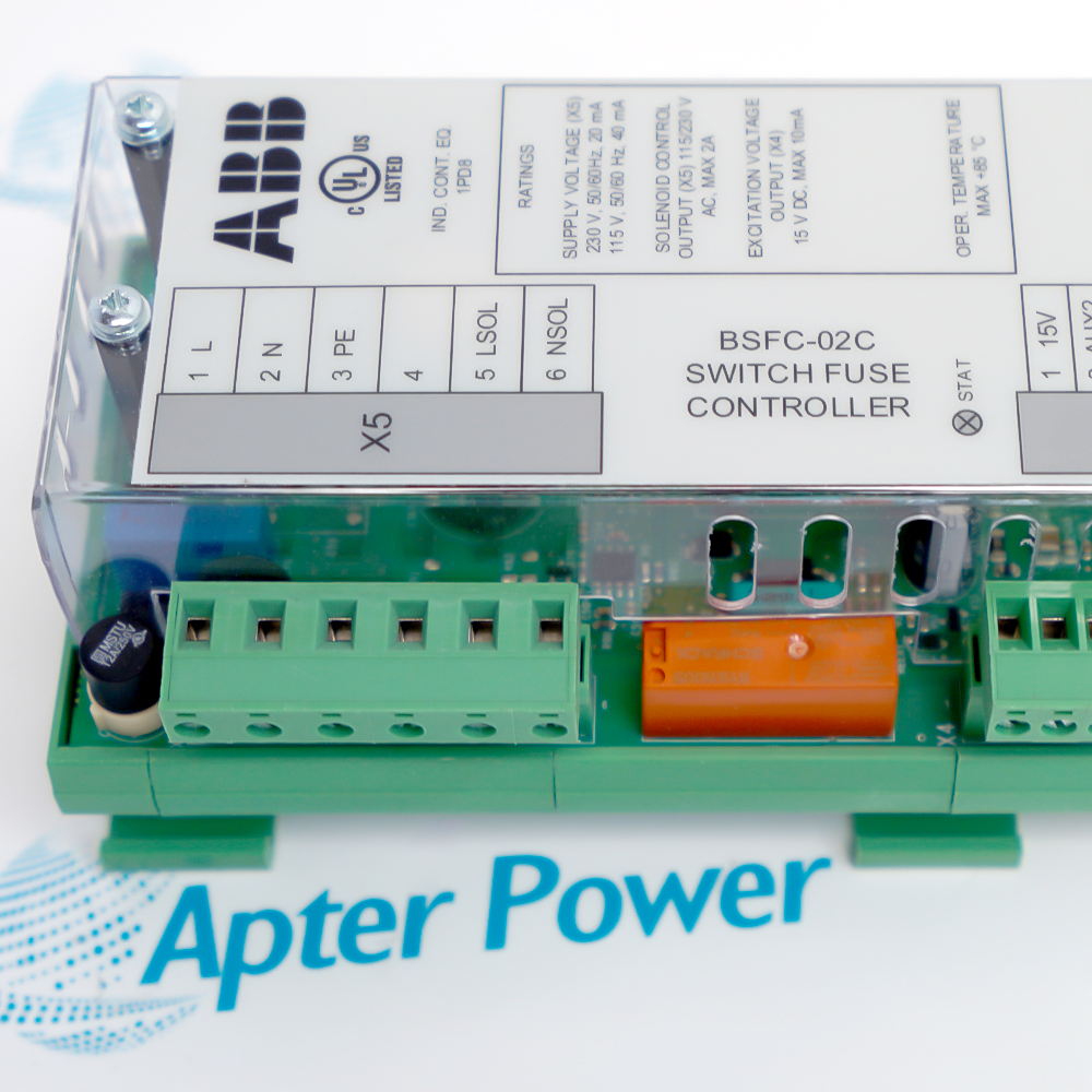
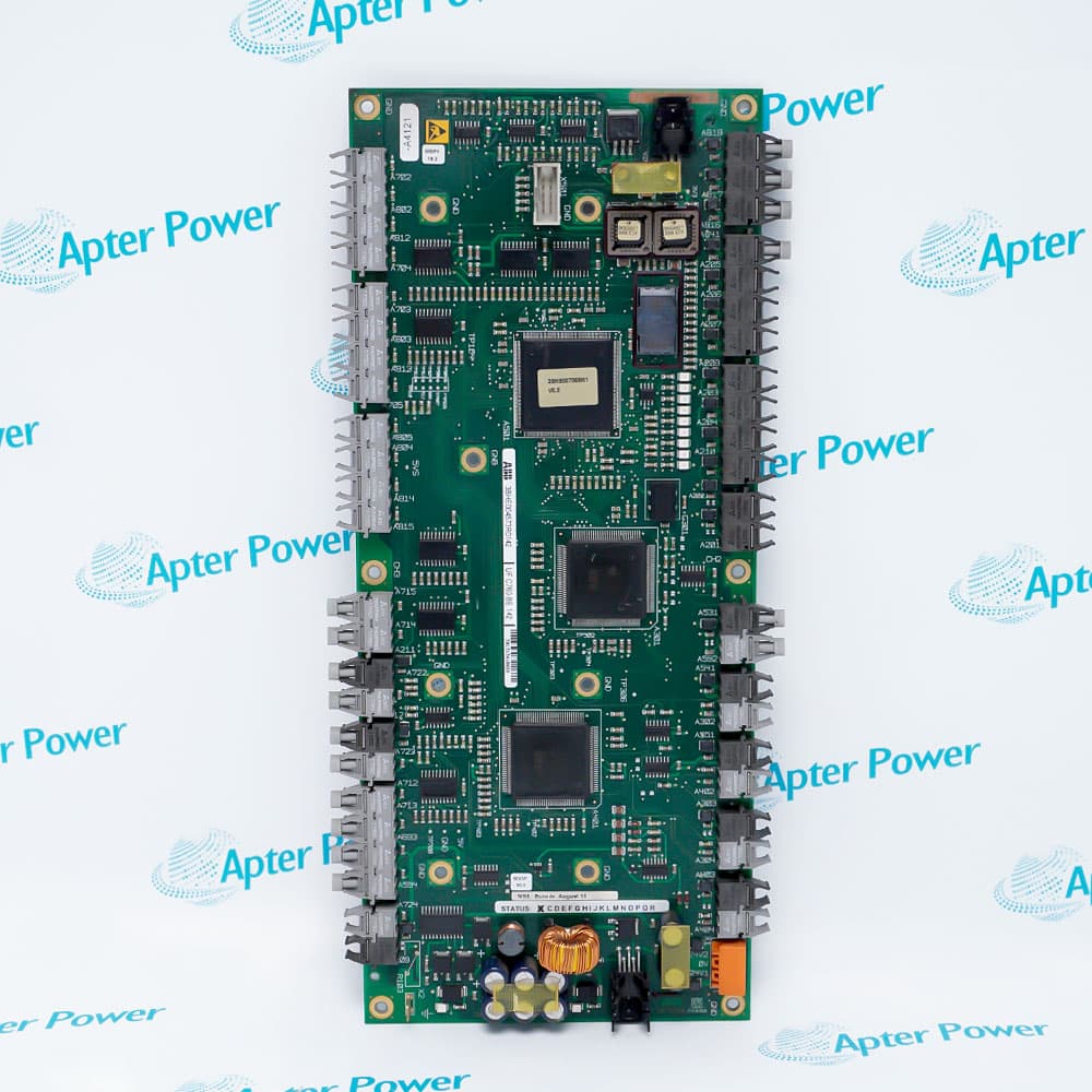
Match BSFC-02C and 3AXD50000011461 to the installed charging controller. Compare X4/X5 terminals, optical ports V1–V6, front labels and the actual cabinet wiring.
-
Check the offered item before ordering
Request current photos of the full marking, front switches, optical connectors and terminal assembly. Confirm what accessories are included in the quotation before ordering.
Technical specifications for BSFC-02C 3AXD50000011461
-
Manufacturer:ABB
-
Product Category:General Automation
-
Spare Part Number:3AXD50000011461
-
Weight:0.32 kg
-
Tariff Code:8537101190
-
Controller family:BSFC-02C
-
Power input (X5):115 V AC or 230 V AC ±10%
-
Supply frequency:50/60 Hz
-
Typical input current:40 mA at 115 V AC; 20 mA at 230 V AC
-
X5 input fuse:2 A slow microfuse
-
X5 terminal block:6-position detachable screw; ≤2.5 mm² wire
-
Solenoid-control voltage:115 V AC or 230 V AC, +10/−15%
-
Solenoid-control current:2 A max for 3.5 s; 4 A max for 20 ms
-
Switch feedback (X4):15 V DC output; 10 mA max
-
X4 terminal block:4-position detachable screw; ≤2.5 mm² wire
-
Optical ports:V1–V6
-
Optical interface:Avago Versatile Link, 5 MBd
-
Plastic optical-fiber length:4 m maximum
-
Minimum fiber bend radius:35 mm
-
Operating temperature:0–70 °C, free air circulation
-
Mounting rail:35 mm, vertical or horizontal
-
Conformal coating:Standard
Information
- The BSFC-02C coordinates the charging circuit and inverter enable sequence in an air-cooled ACS880 multidrive installation. Its terminal and fiber connections link the controller with the installed power equipment.
Interface separation: Uses X4/X5 electrical terminals and V1–V6 optical paths for distinct functions.
Service continuity: Retain front-switch positions and original cabinet connection records.
Optical connections V1–V6 are specified as 5 MBd Avago Versatile Link transmitters and receivers. The plastic optical fiber run between the controller and inverter modules is limited to 4 m. ABB also specifies a 35 mm minimum fiber bend radius; connector cleanliness and routing affect reliable command transfer.
The unit mounts on a 35 mm rail and is specified for 0–70 °C with free air circulation. The BSFC-12C shares parts of the family layout but uses a 24 V DC input, so its electrical figures must not be substituted for the BSFC-02C AC-powered column.
BSFC-02C 3AXD50000011461 BSFC-02C Original Hardware Manual Excerpt
ABB original BSFC-02C hardware, connector and technical-data pages. PDF · 7 pages.BSFC-02C 3AXD50000011461 Installation & Verification Guide
Model-specific field checks, circuit identification, optical links and acceptance records. PDF · 2 pages.
Application scope: These checks cover the charging controller, its electrical and optical interfaces, and the approved inverter switching sequence.
Air-cooled multidrive charging
Coordinate the charging supply and DC switch arrangement specified for air-cooled ACS880 inverter modules.Inverter optical control
Connect the designated inverter optical branches without exchanging V1–V6 assignments.Power-switch feedback
Use the X4 feedback path to confirm switch state in the controller sequence.Service replacement
Preserve switch settings, terminal mapping and the approved power-up procedure when replacing the controller.
Follow the drive electrical-safety procedure and prove the DC link discharged before touching X4, X5 or optical branches.
Verify the BSFC-02C supply column and do not apply BSFC-12C 24 V DC wiring assumptions.
Identify V1–V6 and the destination inverter module before disconnecting each fiber.
Handle connectors, keep end faces clean and maintain at least the specified bend radius.
Photograph and record S1–S3 and terminal-block positions before removing the unit.
After controlled energization, confirm feedback, optical indications and the expected inverter switch-on and switch-off steps.
Alternative Names
Technical notes
Power input: X5 accepts the AC supply; select 115 V or 230 V as installed and verify frequency and fuse.
Switch feedback: X4 provides a low-voltage feedback source; preserve its assignment and the actual switch-state comparison.
Solenoid output: Use the appropriate AC control voltage and observe the short-duration current limits.
Technical reference: ABB hardware manual 3AXD50000027498 Rev C; material code association from ABB ACS880 retrofit handbook.

FAQ View All FAQ
-
How should the AC supply for BSFC-02C 3AXD50000011461 be checked before energization?Measure the actual X5 supply under the approved maintenance procedure and verify that the voltage and frequency agree with the BSFC-02C column, then check the cabinet fuse and wiring.
-
Why must BSFC-12C not replace BSFC-02C 3AXD50000011461 without an engineering review?BSFC-12C uses a different 24 V DC supply. Compare the complete power, feedback, solenoid and optical arrangements before considering any substitution.
-
Which record prevents V1–V6 optical mix-ups on BSFC-02C 3AXD50000011461?Label each cable with its BSFC port and destination inverter module before removal, then compare the restored mapping with the cabinet drawing and operating indications.
-
How is the switch-feedback path on BSFC-02C 3AXD50000011461 proven after reconnection?Use the approved charge-sequence test to compare the X4 feedback indication with the actual power-switch state. Investigate disagreement before enabling inverter operation.
-
What limits govern optical-fiber routing from BSFC-02C 3AXD50000011461?Keep the controller-to-inverter plastic optical fiber within the 4 m limit and maintain a bend radius of at least 35 mm. Inspect connectors for dirt or damage.
-
What must be retained when removing BSFC-02C 3AXD50000011461 from its rail?Record the complete marking, S1–S3 positions, X4/X5 terminal assignments, optical-port map and cabinet reference before releasing the 35 mm mounting feet.
-
How should a failed solenoid-control test on BSFC-02C 3AXD50000011461 be investigated?Check the X5 supply and common slow 2 A fuse, verify the coil wiring and inspect switch feedback. Apply the cabinet procedure rather than bypassing the charge interlock.
-
What acceptance evidence is needed after fitting BSFC-02C 3AXD50000011461?Retain as-found and as-left wiring photos, supply and feedback readings, optical-port mapping, controller indicators and the controlled power-switch sequence result.
Supporting new and legacy automation
-
Please try to be as accurate as possible with your search.
-
We can quote you on 1000s of specialist parts, even if they are not listed on our website.
-
We can't find any results for “”.
Related cases and sourcing guidance
View all case studiesYou May Also Like
Product Browsing History
-
Whatsapp: +86 18030235313
Send us a message. -
sales13@apterpower.com
Complete our online form. -
+86 18030235313
Speak to our team in your native language.