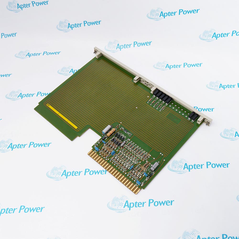
-
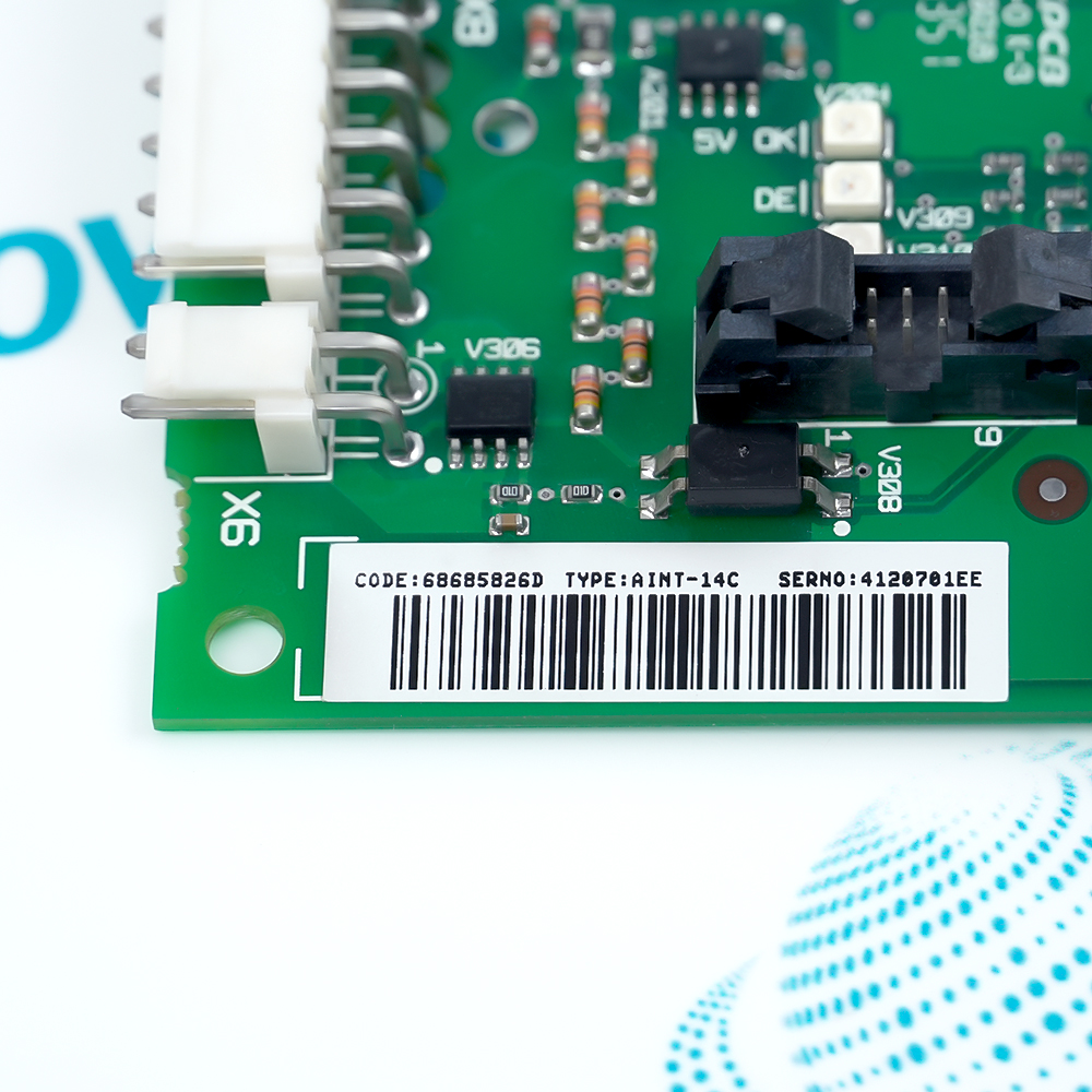
Match the complete marking
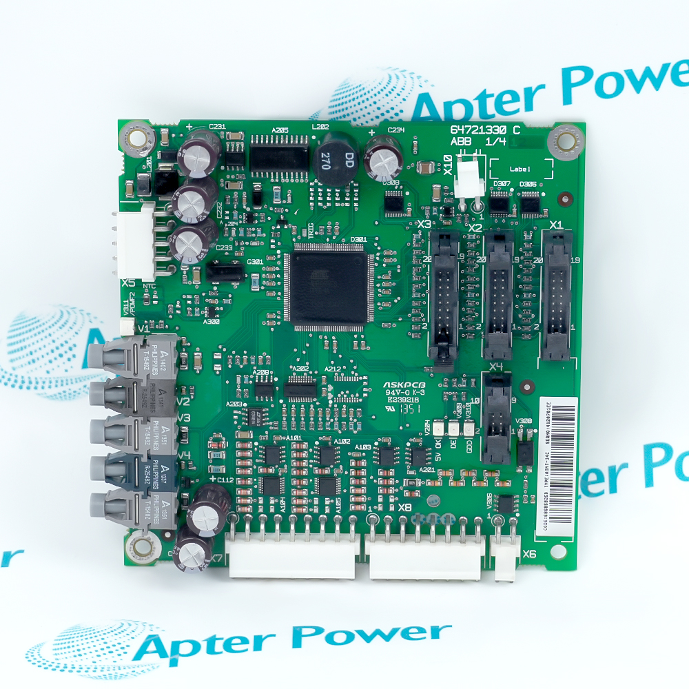
Include AINT-14C and every revision or approval marking visible on the item. Keep the exact reference on your enquiry and quotation. -
Check the offered item before ordering
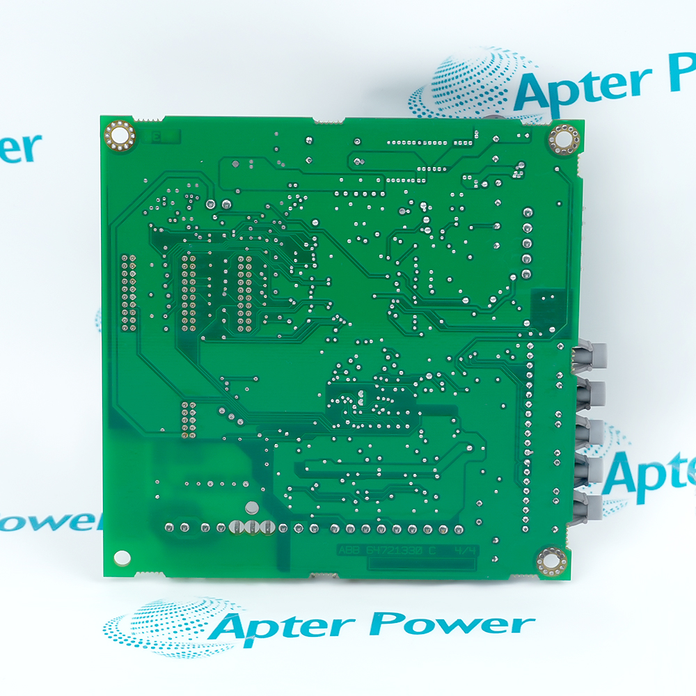
Request available label and interface photos. Have your maintenance team compare the offered AINT-14C reference with the installed equipment and applicable ABB documentation.
Technical specifications for AINT-14C
-
Manufacturer:ABB
-
Product Category:Servo Drives
-
Spare Part Number:AINT-14C
-
Weight:0.1 kg
-
Tariff Code:8537101190
-
Drawing position:A42
-
Converter sections:2 documented locations: grid-side and rotor-side
-
Interface medium:PPCS optical links
-
Gate-driver path:3-phase converter interface
Information
- The complete AINT-14C identity establishes the hardware selection; installation still depends on the documented host, companion components and project configuration.
Fiber-link preservation: Retain transmitter/receiver direction and channel labeling.
Gate-interface boundary: Do not energize until control and gate-driver connections match the circuit diagram.
Optical PPCS links and local electrical connectors are directional. Record board position, fiber channel and mating boards before disconnecting any cable.
Acceptance should verify control-board communication, gate-interface diagnostics and converter-ready status before any controlled power-stage test is attempted.
-
ABB AINT-14C technical reference
Apter Power reference with verified manufacturer data and exact-model applicability. -
ABB AINT-14C engineering guide
Apter Power installation, configuration, diagnostic and acceptance guidance.
Platform applications: The uses below depend on the installed controller configuration and approved system design.
-
Grid-side converter interface
Link control electronics with the documented grid-side power stage. -
Rotor-side converter interface
Serve the documented rotor-side converter modules. -
PPCS optical communication
Carry directional optical control and feedback channels. -
Power-stage maintenance
Replace the exact board while preserving gate-driver and control connections.
Match every field of AINT-14C with the approved spare-parts record before installation.
Use grounded handling, antistatic packaging and protected work surfaces for exposed electronics.
Confirm connector keying, slot assignment, supply and companion hardware before energizing.
Record switches, firmware, parameters, terminal assignments and as-found diagnostics before removal.
Check contamination, corrosion, ventilation, vibration and cabinet temperature before fitting the replacement.
Complete the manufacturer and site acceptance procedure, then retain the as-left result with the maintenance record.
Alternative Names
Technical notes
Position relationship: Confirm whether AINT-14C belongs to the grid-side or rotor-side A42 location and preserve the exact connector and PPCS fiber assignment.
Signal boundary: Treat the board as the control-to-gate-driver interface; inspect optical connectors and maintain fiber routing without applying power-stage ratings to the board.
Technical reference: ABB ACS800-67 Wind Turbine Converters Hardware Manual.

FAQ View All FAQ
-
How should the optical channels of AINT-14C be recorded?Label each transmitter and receiver fiber by channel and destination, then photograph the routing before removal.
-
What should be checked if AINT-14C reports a converter-side communication fault?Inspect fiber seating and direction, control-board status, local power, gate-driver connections and the configured converter section.
-
Why must the installed converter side be known before replacing AINT-14C?ABB uses the board in grid-side and rotor-side assemblies whose companion boards and channel maps differ.
-
What is the safe acceptance sequence for AINT-14C?Verify power-off continuity and optical routing, energize control power, clear diagnostics and follow the approved converter test before enabling the power stage.
-
What evidence should be recorded before replacing AINT-14C?Capture the complete nameplate, installed slot or mounting position, companion hardware, wiring identifiers and the accepted operating baseline for the main-circuit interface board.
-
How should an intermittent fault around AINT-14C be isolated?Separate field wiring, connector, supply, grounding, configuration and host-system causes. Reproduce the symptom under a controlled test and change only one variable at a time.
-
What configuration evidence should be retained after commissioning AINT-14C?Retain the hardware identity, firmware or parameter record where applicable, channel assignment, as-left measurements, alarm or diagnostic state and the approved functional-test result.
-
When should AINT-14C be rejected during incoming inspection?Quarantine the item if the complete marking, connector keying, board revision, protective coating, terminal condition or required companion hardware differs from the approved replacement record.
Supporting new and legacy automation
-
Please try to be as accurate as possible with your search.
-
We can quote you on 1000s of specialist parts, even if they are not listed on our website.
-
We can't find any results for “”.
Related cases and sourcing guidance
View all case studies-
28 ABB BRC410 Units: Ready to Inspect, Collected on Order DayRead case > -
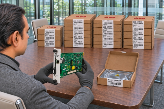
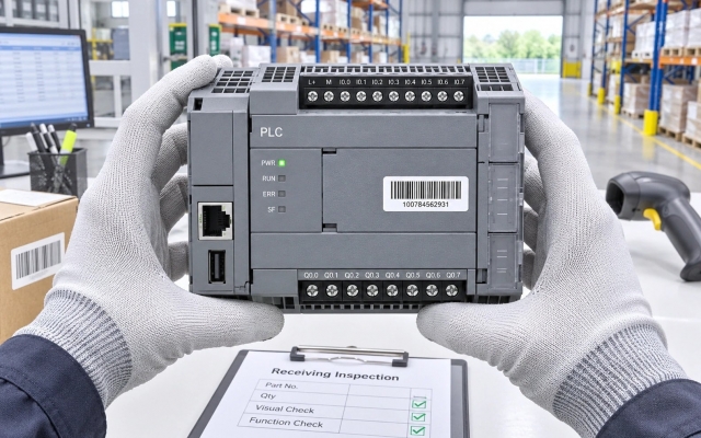
Receiving Inspection and Acceptance of Replacement Control ModulesRead case > -
Honeywell FC-RUSIO-3224 Delivered for an Oman Government ProjectRead case > -
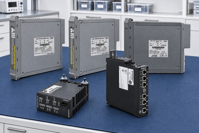
GE Mark & ICS Triplex Spares: Supporting Production RecoveryRead case >
You May Also Like
Product Browsing History
-
Whatsapp: +86 18030235313
Send us a message. -
sales13@apterpower.com
Complete our online form. -
+86 18030235313
Speak to our team in your native language.