-
Match the complete marking
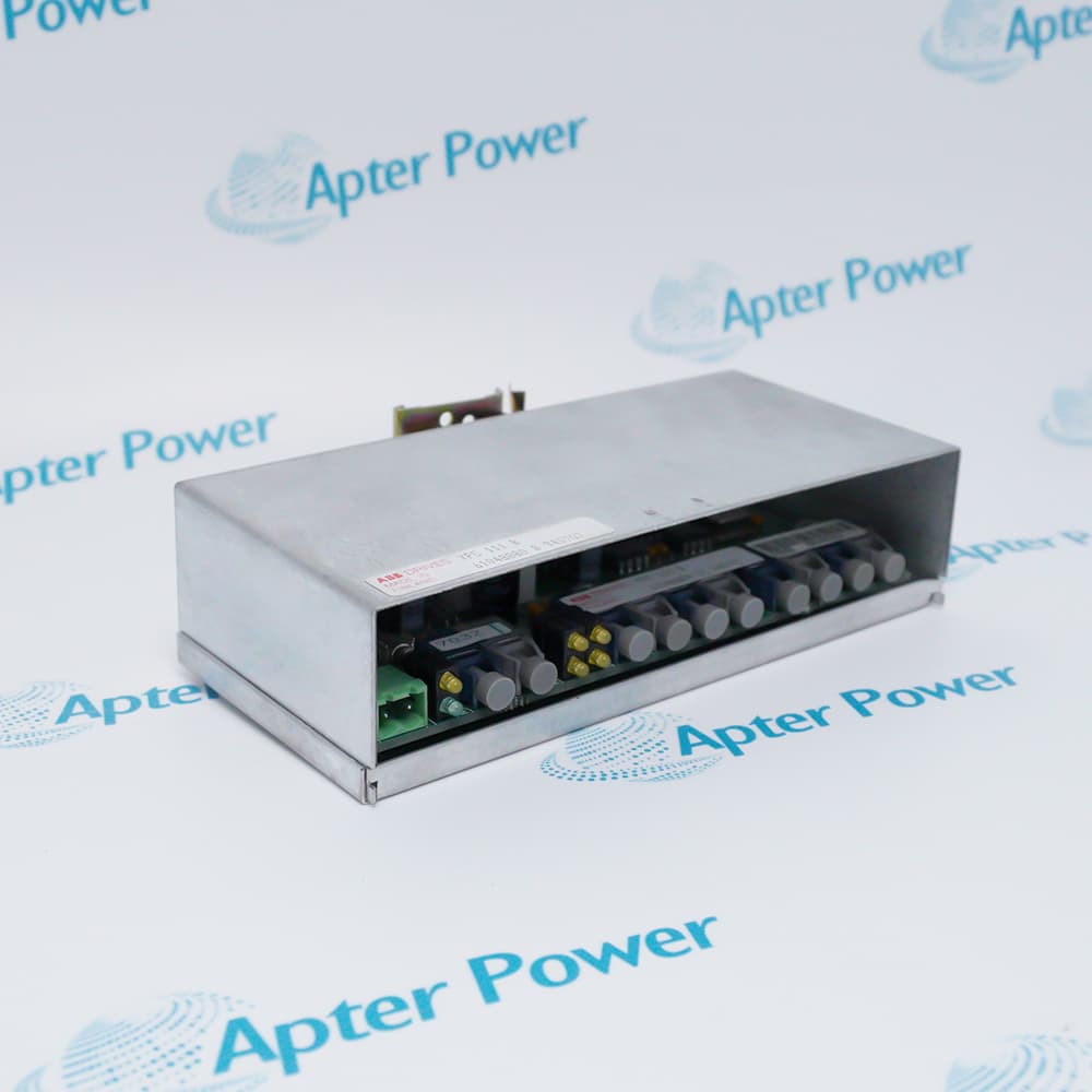
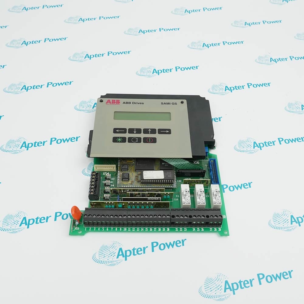
Match the complete ABB SDCS-IOB-22 3BSE005177R1 marking and installed configuration. Confirm SDCS-IOB-22, 3BSE005177R1 and the field terminal assignments.
-
Check the offered item before ordering
Request available label and connector photos. Have your maintenance team compare the offered SDCS-IOB-22 3BSE005177R1 with the installed equipment and applicable ABB documents.
Technical specifications for SDCS-IOB-22 3BSE005177R1
-
Manufacturer:ABB
-
Product Category:DCS Systems
-
Spare Part Number:SDCS-IOB-22 3BSE005177R1
-
Weight:0.34 kg
-
Tariff Code:8537101190
-
Digital inputs:8, optocoupled
-
Nominal input voltage:115 V AC
-
Input resistance:22 kohm
-
Logic 0 input range:0–20 V
-
Logic 1 input range:60–130 V
-
Input filter, channels 1–6:10 ms time constant
-
Input filter, channels 7–8:2 ms time constant
-
Relay outputs:6 normally open
-
Open-collector outputs:2; 24 V DC external, 50 mA maximum
-
Relay AC rating:250 V AC / 3 A maximum
-
Relay DC rating:24 V / 3 A or 115/230 V / 0.3 A maximum
-
Digital terminal capacity:Up to 4 mm²
Information
- ABB SDCS-IOB-22 3BSE005177R1 adapts field command and status circuits to the drive control board. Input thresholds, channel filtering and output technology differ, so each circuit must be matched to its assigned function rather than treated as a generic digital point.
Output mix: Relay contacts and isolated open-collector channels
Diagnostics: Local indication of signal states
The last two input channels have a shorter filter time constant than the first six. Preserve the assigned channel when timing matters, because moving the same external signal to another terminal can alter its effective response. Status LEDs assist investigation but do not prove the control function has been accepted by the drive.
The output group combines six relay contacts with two optically isolated open-collector circuits. Relay and transistor loads require different supply, current and protection checks. Mount and connect the board as the specified external I/O arrangement, preserving the control-board connection and field wiring.
SDCS-IOB-22 3BSE005177R1 Original Technical Excerpt
ABB DCS600 System Description, 3ADW000072R0601; DCS500B/DCS600 Service Manual, 3ADW000093R0801. Selected original pages retain the relevant technical context. PDF · 3 pages.SDCS-IOB-22 3BSE005177R1 Installation & Verification Guide
Apter Power installation workbook covering separate field voltage classes, inspect external board installation, validate input thresholds and timing, testing and handover. PDF · 5 pages.
Application scope: The applications describe the complete signal or control path. Confirm the intended function and interface; accessories are supplied only when itemized.
AC command interfacing
Bring compatible 115 V AC field commands into the drive control arrangement.Drive status switching
Operate suitable external status circuits through the assigned relay contacts.Low-current DC signaling
Use the open-collector outputs with correctly supplied DC circuits.Existing DC-drive maintenance
Restore the original I/O function mapping and field connections.
Identify the actual input supply and distinguish relay loads from open-collector loads. Record the software function of each point before isolating the drive and external circuits.
Check mounting, control-board cable and field-terminal engagement. Preserve the intended external I/O architecture and avoid transferring analog-board wiring to the digital interface.
Apply controlled field states and compare the measured voltage with the defined logic bands. Check the faster channels separately when the assigned function depends on response time.
Use a test method appropriate to each output technology. Confirm external DC supply and current for open-collector points and actual contact operation for relay points. Review load protection and polarity.
Exercise the required command, status and shutdown paths through the drive program. Remove temporary test states and retain the final channel-function map.
Retain the final tested settings, physical connection and accepted process response for SDCS-IOB-22 3BSE005177R1.
Alternative Names
Technical notes
Voltage-version boundary: The IOB-22 input voltage and impedance must not be replaced by values belonging to IOB-21 or IOB-23.
Filter timing: Channel assignment affects input filtering. Review a moved signal against the 10 ms and 2 ms groups.
Output technology: Separate relay-contact circuits from open-collector circuits during load selection and testing.

FAQ View All FAQ
-
Why must the input-voltage execution of SDCS-IOB-22 3BSE005177R1 be checked before reconnection?The related IOB-21 and IOB-23 boards use different voltage levels and input impedances. Matching the board family or connector alone is insufficient.
-
Can a timing-sensitive input be moved freely between channels of SDCS-IOB-22 3BSE005177R1?No. Channels 7 and 8 have a shorter filter time constant than channels 1–6. Preserve the channel assignment or review the resulting timing.
-
How should a voltage between the stated logic bands of SDCS-IOB-22 3BSE005177R1 be treated?It is not a defined acceptance point for a stable zero or one. Investigate the source circuit and voltage drop rather than relying on an occasional LED state.
-
What distinguishes the two open-collector outputs on SDCS-IOB-22 3BSE005177R1 from its relay outputs?They need the appropriate external DC circuit and have a much lower current limit. Do not connect a relay-contact load to an open-collector terminal without redesign.
-
Why can an input LED on SDCS-IOB-22 3BSE005177R1 be correct while the drive command is wrong?The software function assigned to that input may differ from the expected command. Check both the electrical state and drive parameter assignment.
-
How should relay DC switching duty be assessed for SDCS-IOB-22 3BSE005177R1?Use the rating for the actual DC voltage; the allowable current at higher DC voltage is lower than the 24 V rating.
-
Does output protection on SDCS-IOB-22 3BSE005177R1 remove the need to review the external load?No. Protection components do not make every load compatible. Evaluate supply, current, inductive behavior and required field protection.
-
What must be tested after the control-board connection to SDCS-IOB-22 3BSE005177R1 is restored?Verify each assigned input and output through the drive software and physical field response, including permissives and required shutdown states.
Supporting new and legacy automation
-
Please try to be as accurate as possible with your search.
-
We can quote you on 1000s of specialist parts, even if they are not listed on our website.
-
We can't find any results for “”.
Related cases and sourcing guidance
View all case studiesYou May Also Like
Product Browsing History
-
Whatsapp: +86 18030235313
Send us a message. -
sales13@apterpower.com
Complete our online form. -
+86 18030235313
Speak to our team in your native language.