Speak to a sourcing specialist
sales13@apterpower.com

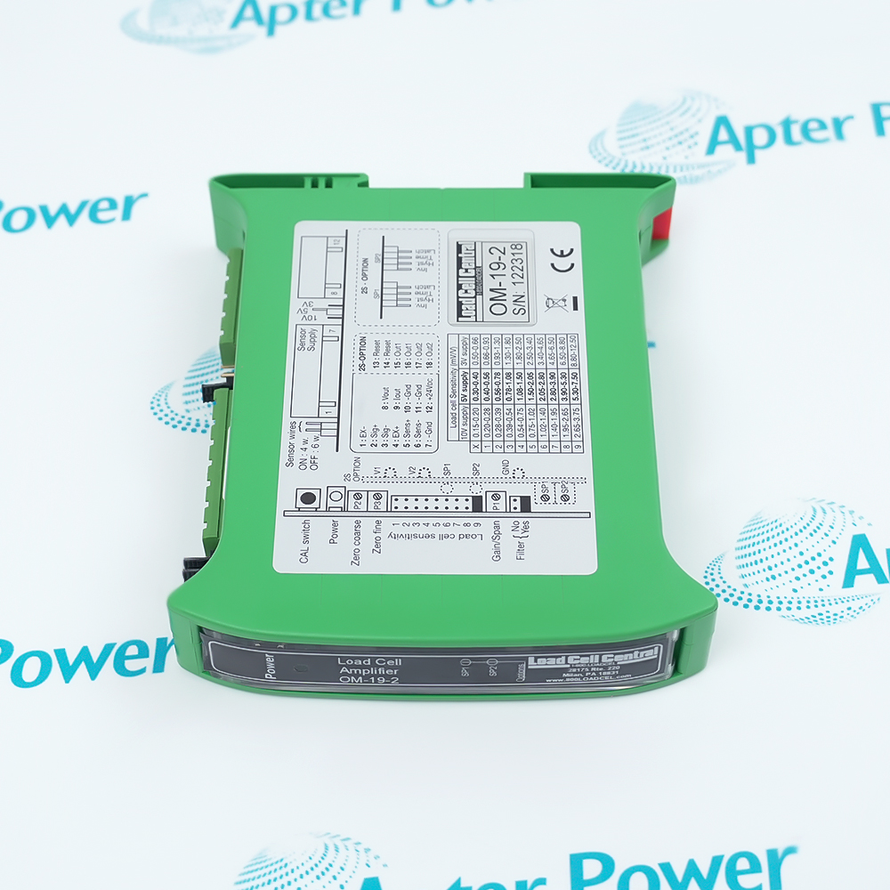
OM-19-2

DIN-Rail Load Cell Signal Conditioner
 OM-19-2
 OM-19-2
 OM-19-2
 OM-19-2
 OM-19-2
 OM-19-2
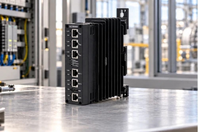
Product image is representative; revision or series may vary. Contact us to request a specific version.

Product Describe:

Load Cell Central OM-19-2 converts a strain-gauge bridge signal into a configured voltage or 4–20 mA output.
  • Manufacturer part number
    OM-19-2
  • Shipping
    Swift global dispatch
  • Condition
    New, original product
  • Shipping size (est.)
    11.8cm x 10cm x 2.2cm
  • Country of Origin
    USA
Get a quick price for OM-19-2
E-mail *
Mobile *
Company
Content *
Quantity *
Upload (gif, jpg, jpeg, png, bmp, doc, docx, xls, xlsx, ppt, pdf, csv)
For more information on how your data is processed and stored by Apterpower please read our privacy policy

What happens after you enquire

  • 0

    Review your reference

    Send the complete OM-19-2 reference, label photos and required quantity. Inspect OM-19-2 identity, DIN mounting, jumpers and terminals.

  • 1

    Confirm the offer

    Review the offered execution, condition and included items for OM-19-2. Confirm the conditioner; cells, junction box and relay options only when itemized in the quotation.

  • 2

    Arrange dispatch

    Swift global dispatch. Confirm quantity, dispatch date and delivery details for OM-19-2 in the quotation.

  • Match the complete marking

    Match the complete Load Cell Central OM-19-2 marking and installed configuration. Inspect OM-19-2 identity, DIN mounting, jumpers and terminals.

  • Check the offered item before ordering

    Request available label and connector photos. Have your maintenance team compare the offered OM-19-2 with the installed equipment and applicable Load Cell Central documents.

Technical specifications for OM-19-2

  • Product Category:
    General Automation
  • Spare Part Number:
    OM-19-2
  • Weight:
    0.1 kg
  • Tariff Code:
    8537101190
  • Standard supply:
    24 ±4 V DC
  • Excitation:
    3 / 5 / 10 V DC
  • Minimum bridge impedance:
    80 Ω at 3/5 V; 160 Ω at 10 V
  • Sensitivity adjustment:
    0.15–12 mV/V
  • Voltage output:
    ±10 V / 0–10 V
  • Current output:
    4–20 mA
  • Voltage-load impedance:
    ≥2000 Ω
  • Current-load impedance:
    ≤500 Ω
  • Output capacitance:
    ≤1 nF
  • Low-pass filter:
    10 Hz at −3 dB

Information

Overview Downloads Applications / Compatibility Product Precautions
  • Load Cell Central OM-19-2 combines bridge excitation, zero/span adjustment and analog conversion. Bridge impedance, sense wiring and receiver loading must be assessed together.
Signal path: Excited bridge to analog output
Adjustment: Jumper selection and zero/span controls
Load constraint: Excitation-dependent impedance
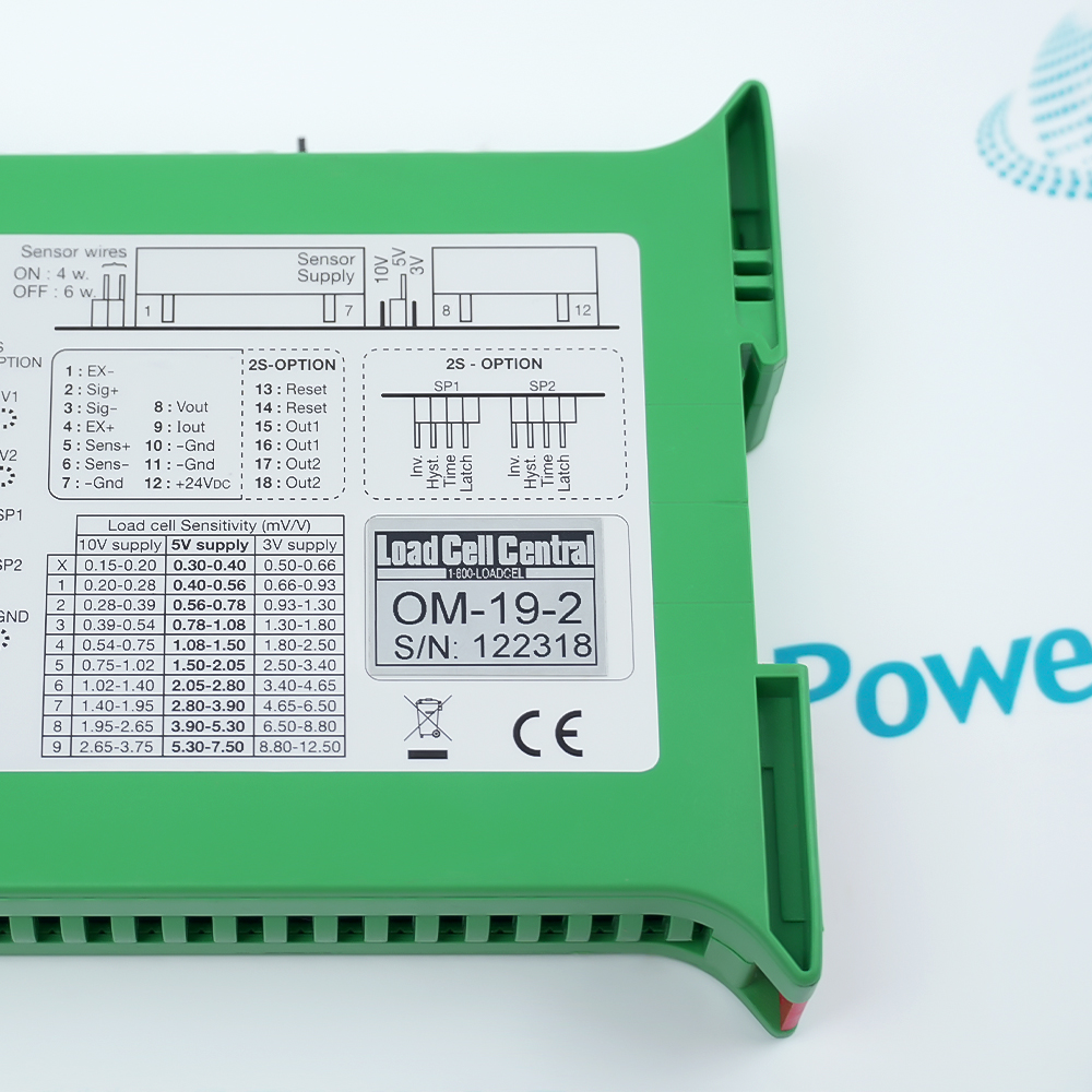
Standard supply is 24 ±4 V DC. Excitation selects 3, 5 or 10 V, with minimum bridge impedance of 80 Ω at 3/5 V and 160 Ω at 10 V. Four parallel 350 Ω cells therefore require the lower-excitation impedance allowance.

Four- and six-wire load-cell connections are supported. Establish the correct sense arrangement before calibrating against known loads. The 0.15–12 mV/V sensitivity adjustment matches bridge output to the receiving scale.

Choose ±10 V, 0–10 V or 4–20 mA output and respect receiver impedance and output-capacitance limits. Engage the 10 Hz filter only when its response suits the process. Separate OM-192S set-point relay functions are not inferred from this identity.
Controller platform reference: OM-19 strain-gauge conditioning. Follow the applicable installation instructions and approved design.
Technical and service documents for Load Cell Central OM-19-2, separating original engineering information from the installation and verification workflow.
Original manufacturer pages retain their technical context. Use the Apter Power guide with the applicable manufacturer instructions and approved installation design.
System and supply context: Load Cell Central OM-19-2 is used with OM-19 strain-gauge conditioning. Companion equipment and interfaces must match the installed arrangement.

Application scope: These applications describe the intended system function. Select the actual configuration for that function; accessories are included only when itemized.
Prepare Load Cell Central OM-19-2 for its configured installation using these checks.
Calculate bridge loading

Identify cell sensitivity and resistance, calculate parallel impedance and choose permissible excitation. Preserve the mechanical reference and receiver scale.

Connect excitation and sense

Use the correct four/six-wire scheme, verify polarity and inspect shielding and junctions. Confirm stable bridge excitation before adjustment.

Calibrate zero and span

Choose the sensitivity range, establish unloaded zero and apply known loads. Check intermediate points and repeatability after adjustment.

Match the analog receiver

Select voltage/current output, verify scale and impedance and include cable capacitance. Compare local and remote readings under controlled loads.

Tune response and archive settings

Evaluate filtering with dynamic loads, retaining the fastest acceptable response. Save jumpers, calibration results and a separate shunt baseline.

Configuration handover

Retain the final tested settings, physical connections and accepted operating response for OM-19-2.

Alternative Names

Load Cell Central OM-19-2

Technical notes

Bridge loading: Calculate parallel resistance before selecting excitation; cell count alone does not qualify 10 V.

Calibration sequence: Establish excitation and wiring before adjusting known-load zero/span.

Receiver assessment: Check loading, capacitance and dynamic response at the destination.

FAQ View All FAQ

  • Can four parallel 350 Ω cells use 10 V excitation from OM-19-2?
    Their combined 87.5 Ω is below the 160 Ω minimum at 10 V. Assess 3/5 V excitation and verify the resulting signal and calibration.
  • Why is four-wire versus six-wire selection important on OM-19-2?
    Sense wiring affects excitation reference. Follow the selected scheme and calibrate with the actual cables and cells.
  • What can cause OM-19-2's current output to fail near full scale?
    Excessive loop impedance can exceed 500 Ω. Measure wiring plus receiver load before altering calibration.
  • How can a low-impedance voltage receiver affect OM-19-2?
    Voltage loading must be at least 2000 Ω. Verify receiver impedance and compare the output locally and at its destination.
  • When should filtering be enabled on OM-19-2?
    Use it when noise reduction is compatible with process response. Test settling with representative load changes.
  • Does a shunt check replace known-load calibration of OM-19-2?
    It checks an electrical response, not the full mechanical load path. Perform known-load calibration and repeatability checks separately.
  • Can set-point relays be assumed on OM-19-2?
    No. Those specifications belong to OM-192S. Inspect actual hardware before assigning relay functions.
  • Why assess cable capacitance at OM-19-2's output?
    The capacitive-load limit is 1 nF. Assess cable and receiver together and verify stability before masking a wiring problem with filtering.
SPEAK TO OUR TEAM
Let’s find the right solution for you.
Send us the part number, quantity and delivery destination. Our team will help confirm availability and lead time.
  • Whatsapp: +86 18030235313

    Send us a message.
  • sales13@apterpower.com

    Complete our online form.
  • +86 18030235313

    Speak to our team in your native language.