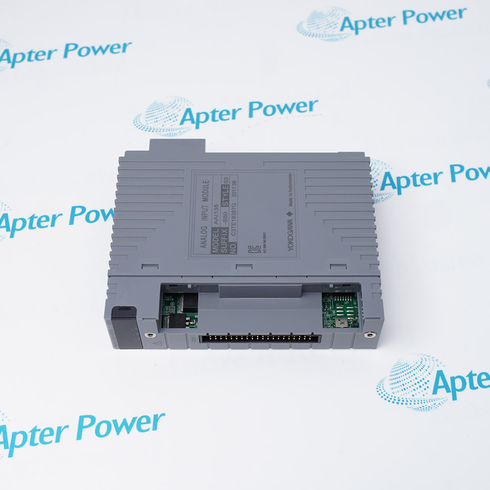
-
Match the complete marking
Include AAT141-S00 S2 and any revision or assembly number visible on the item. Keep the exact reference on your enquiry and quotation.
-
Check the offered item before ordering
Request available label and connector photos. Have your maintenance team compare the offered AAT141-S00 S2 with the installed equipment and applicable Yokogawa documentation.
Technical specifications for AAT141-S00 S2
-
Manufacturer:Yokogawa
-
Product Category:DCS Systems
-
Spare Part Number:AAT141-S00 S2
-
Weight:0.18 kg
-
Tariff Code:8537101190
-
I/O role:Temperature / millivolt input
-
Reference design:AAT141-S
-
Channels:16 isolated inputs
-
Thermocouple types:J, K, E, B, R, S, T and N
-
Millivolt ranges:−100 to +150 mV; −20 to +80 mV
-
Channel selection:Thermocouple or mV by channel
-
Update period:1 second
-
TC reference accuracy:±30 µV
Information
- AAT141-S00 S2 receives thermocouple and low-level millivolt signals for process-temperature measurement.
Sensor flexibility: Channel-specific input selection
Service focus: Preserve cold-junction and channel settings
The referenced thermocouple set includes J, K, E, B, R, S, T and N. Two millivolt ranges, −100 to +150 mV and −20 to +80 mV, are documented. The base design updates input data each second, so temperature-control logic and alarming should use the appropriate scan and filtering configuration.
Thermocouple measurement depends on correct sensor type, polarity, cold-junction arrangement and the installed terminal. Yokogawa cautions against grounded thermocouples where multiple ground paths would affect measurement. Preserve the exact module marking and configured channel types during replacement.
-
Yokogawa AAT141-S00 S2 technical reference
Apter Power technical reference - PDF, 2 pages. Product identity, verified characteristics, system role and engineering checks. -
Yokogawa AAT141-S00 S2 installation verification guide
Apter Power installation guide - PDF, 1 page. Pre-installation, configuration, commissioning and acceptance checks.
Compatibility scope: Match the S00 S2 style to the installed node, sensor type, channel configuration, terminal wiring and cold-junction arrangement.
-
Process temperature monitoring
Acquire supported thermocouple signals from furnaces, vessels or process equipment in a configured FIO station. -
Mixed sensor installations
Assign supported TC types independently by channel according to the approved input schedule. -
Low-level voltage acquisition
Measure a suitable millivolt source in one of the documented ranges with proper shielding and reference conditions. -
Temperature I/O restoration
Replace a matching module while retaining cold-junction hardware and the saved channel configuration.
Record each channel thermocouple or mV selection.
Preserve polarity, shielding and separation from power circuits.
Check the installed compensation and terminal arrangement.
Evaluate thermocouple grounding against the project design.
Record input trim and alarm configuration before exchange.
Compare readings with known process or test references after fit.
Alternative Names
Technical notes
Technical basis: Yokogawa GS 33K50F60-50E, Temperature Input Modules for FIO.
Applicability: AAT141-S reference data describes the base module. The S2 style, when present, is retained as the offered marking without an assumed electrical difference.
Integration focus: Thermocouple type, polarity, compensation and alarm configuration must follow the installed measurement channels.

FAQ View All FAQ
-
Why can a temperature reading drift after AAT141-S00 S2 is changed?Check cold-junction compensation, sensor type, terminal seating and channel configuration before judging the module.
-
How can a thermocouple-type mismatch be recognized after replacing AAT141-S00 S2?Compare the configured type with the fitted sensor and a known reference temperature; a mismatch can produce a systematic reading error even when wiring is intact.
-
What should be checked when a reading on AAT141-S00 S2 has reversed polarity?Inspect the thermocouple polarity and terminal wiring against the original channel schedule.
-
Why should grounded thermocouples be reviewed for AAT141-S00 S2?Multiple ground paths can disturb low-level thermocouple measurement; use the wiring arrangement approved for the application.
-
How should an open-sensor indication on AAT141-S00 S2 be diagnosed?Check sensor continuity, cable joints, terminal seating and the configured channel type.
-
Can a millivolt channel on AAT141-S00 S2 be treated as a current input?No. The documented choices are thermocouple and specified millivolt ranges, not a general 4–20 mA input.
-
What timing should be considered for alarms sourced through AAT141-S00 S2?The reference data update is one second; include the configured filtering and process response in alarm design.
-
What must be transferred when replacing AAT141-S00 S2?Preserve each channel type, range, cold-junction arrangement, alarm limits and relevant calibration settings.
Supporting new and legacy automation
-
Please try to be as accurate as possible with your search.
-
We can quote you on 1000s of specialist parts, even if they are not listed on our website.
-
We can't find any results for “”.
You May Also Like
Product Browsing History
-
Whatsapp: +86 18030235313
Send us a message. -
sales13@apterpower.com
Complete our online form. -
+86 18030235313
Speak to our team in your native language.