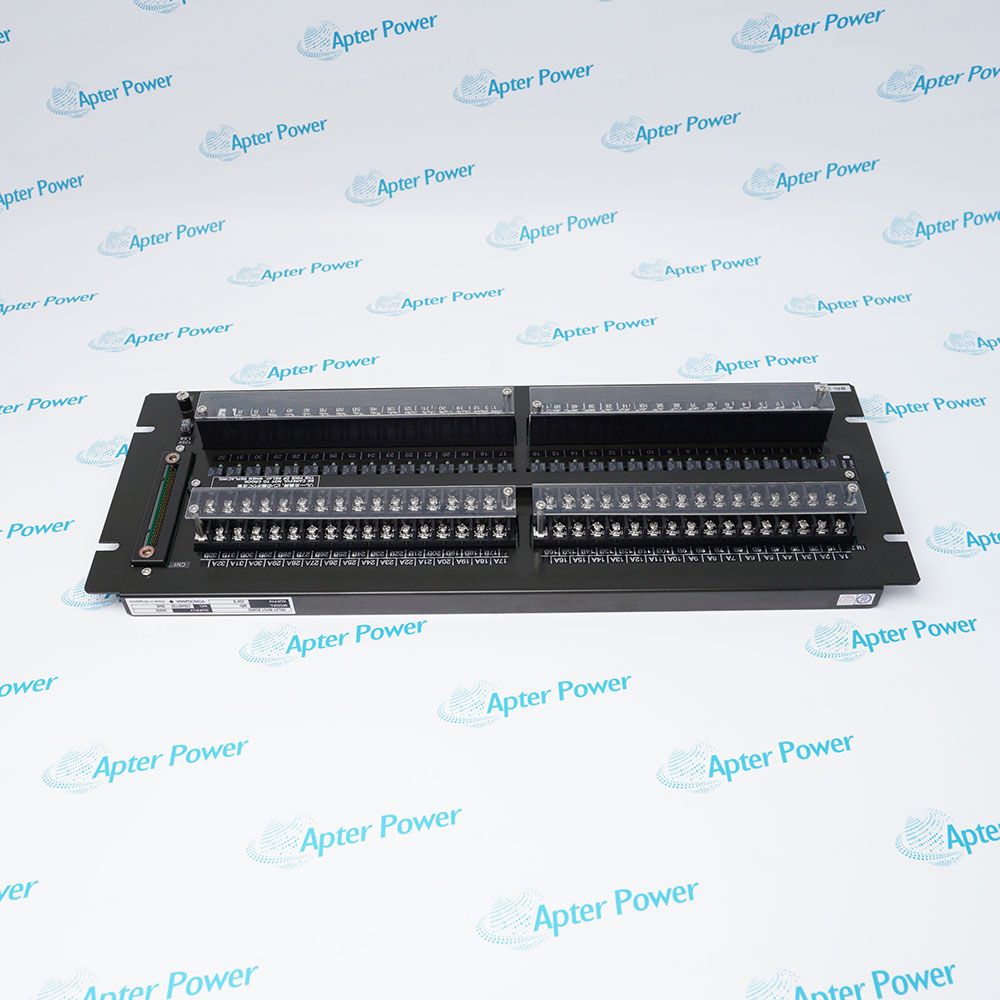
-
Match the complete marking
Include AAI141-S00 S2 and any revision or assembly number visible on the item. Keep the exact reference on your enquiry and quotation.
-
Check the offered item before ordering
Request available label and connector photos. Have your maintenance team compare the offered AAI141-S00 S2 with the installed equipment and applicable Yokogawa documentation.
Technical specifications for AAI141-S00 S2
-
Manufacturer:Yokogawa
-
Product Category:DCS Systems
-
Spare Part Number:AAI141-S00 S2
-
Weight:0.28 kg
-
Tariff Code:8537101190
-
I/O role:Analog input
-
Reference design:AAI141-S
-
Channels:16
-
Signal:4–20 mA
-
Accuracy:±16 µA
-
Data update:10 ms
-
Isolation:Nonisolated input design
-
Installed wiring:Match the approved terminal and transmitter supply arrangement
Information
- AAI141-S00 S2 handles 4–20 mA process inputs in a configured CENTUM FIO station.
Design boundary: Nonisolated input
Configuration: Preserve scaling and loop assignments
The documented analog accuracy is ±16 µA with a 10 ms data-update period. The module supplies process values to the configured field control station; scaling, alarm limits and transmitter health handling belong to the control project rather than the card identity alone.
The complete S00 S2 marking should be compared with the fitted module and terminal hardware. During replacement, retain the channel map and loop wiring, check the transmitter supply architecture and test each affected engineering-unit reading before returning the process to service.
-
Yokogawa AAI141-S00 S2 technical reference
Apter Power technical reference - PDF, 2 pages. Product identity, verified characteristics, system role and engineering checks. -
Yokogawa AAI141-S00 S2 installation verification guide
Apter Power installation guide - PDF, 1 page. Pre-installation, configuration, commissioning and acceptance checks.
Compatibility scope: Match the S00 S2 style to the FIO node, nonisolated loop grounding, terminal hardware and channel configuration.
-
Process-value acquisition
Receive 4–20 mA signals from approved process transmitters in the FIO station. -
Regulatory control feedback
Pass scaled measurements to configured control loops and operator displays. -
Alarm and trend inputs
Supply analog values to the project alarm, history and diagnostic functions. -
Input-module restoration
Restore a verified AAI141 position while retaining loop wiring and scale assignments.
Retain the approved nonisolated-loop grounding design.
Verify each 4–20 mA terminal assignment.
Record engineering-unit range and alarm settings.
Place affected loops in their approved maintenance state.
Verify module style, node and terminal assembly.
Compare known current and displayed value after fit.
Alternative Names
Technical notes
Technical basis: Yokogawa GS 33J60F60-01EN, Analog I/O Modules for FIO.
Applicability: AAI141-S technical figures are reference-design values. Match the complete offered style, host and terminal configuration before applying them.
Integration focus: Because the reference design is nonisolated, review loop commons and grounding with the complete installed circuit.

FAQ View All FAQ
-
How does the isolation design of AAI141-S00 S2 affect installation?AAI141 is documented as nonisolated. Review the system grounding and any required external isolation before connection.
-
What should be checked if a reading on AAI141-S00 S2 is out of scale?Compare transmitter current, terminal polarity, channel scaling, loop wiring and controller diagnostics.
-
Can AAI141-S00 S2 directly substitute for AAI143?No. AAI143 has a different isolation arrangement. Compare the system design and approved replacement list.
-
How should a current-loop open circuit be found on AAI141-S00 S2?Test transmitter supply and current, cable continuity and terminal connections using the site procedure.
-
Why is the module data-update time of AAI141-S00 S2 not the entire control-loop delay?The 10 ms module update is one part of controller scan, filtering, network and field-device response.
-
Which records should be saved before changing AAI141-S00 S2?Retain the channel map, engineering-unit scales, alarm limits and transmitter wiring plan.
-
Can AAI141-S00 S2 be installed in a hazardous-area loop without other design review?No. Apply the approved barrier, grounding and area-classification design for the complete loop.
-
What is a suitable acceptance check after fitting AAI141-S00 S2?Inject or compare a known loop current and verify displayed engineering values and alarm behavior for all affected channels.
Supporting new and legacy automation
-
Please try to be as accurate as possible with your search.
-
We can quote you on 1000s of specialist parts, even if they are not listed on our website.
-
We can't find any results for “”.
You May Also Like
Product Browsing History
-
Whatsapp: +86 18030235313
Send us a message. -
sales13@apterpower.com
Complete our online form. -
+86 18030235313
Speak to our team in your native language.