Speak to a sourcing specialist
sales13@apterpower.com

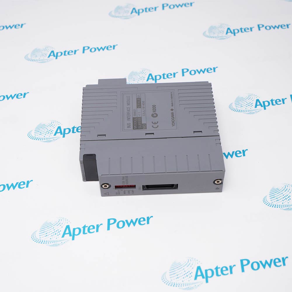
SB401-10 S1

ESB Interface Module
Ships by Friday, November 6
Product image is representative; revision or series may vary. Contact us to request a specific version.

Product Describe:

Yokogawa SB401-10 S1 is an ESB bus interface slave module for CENTUM FIO node communication. It connects the supported node assembly to the ESB path from the control station.
  • Manufacturer part number
    SB401-10 S1
  • Shipping
    Swift global dispatch
  • Condition
    New, original product
  • Shipping size (est.)
    3.2cm × 12.5cm × 13cm
  • Country of Origin
    Japan
Get a quick price for SB401-10 S1
E-mail *
Mobile *
Company
Content *
Quantity *
Upload (gif, jpg, jpeg, png, bmp, doc, docx, xls, xlsx, ppt, pdf, csv)
For more information on how your data is processed and stored by Apterpower please read our privacy policy

What happens after you enquire

  • 0

    Review your reference

    Send the complete SB401-10 S1 reference, label photos and required quantity.
  • 1

    Confirm the offer

    Review the offered revision, condition, included items and documents.
  • 2

    Arrange dispatch

    Confirm quantity, dispatch date, lead-time start and delivery details in the quotation.
  • Match the complete marking

    Include SB401-10 S1 and any series, revision or assembly markings. Keep the complete reference on your enquiry and quotation.
  • Check the offered item before ordering

    Request available label, connector and mounting photos. Have your maintenance team compare the offered SB401-10 S1 with the installed equipment and applicable Yokogawa documentation.

Technical specifications for SB401-10 S1

  • Manufacturer:
    Yokogawa
  • Product Category:
    DCS Systems
  • Spare Part Number:
    SB401-10 S1
  • Weight:
    0.18 kg
  • Tariff Code:
    8537101190
  • Product series:
    CENTUM FIO
  • Reference design:
    SB401
  • Module role:
    ESB bus interface slave
  • Installation context:
    ANB10S / ANB10D node design
  • Bus relationship:
    Node-side ESB interface to FCU
  • Dual node interface arrangement:
    Two SB401 modules
  • Field-signal processing:
    By the separately installed I/O modules
  • Assembly relationship:
    Node base, power supplies and I/O modules

Information

Overview Downloads Applications / Compatibility Product Precautions
  • Yokogawa SB401-10 S1 serves at the node side of the ESB link, allowing the node and its installed modules to exchange information with the field control unit.
Product type: ESB bus interface slave module
System family: CENTUM FIO
Node relationship: ANB10S / ANB10D base configuration
Redundant arrangement: Two interfaces in a dual node
The SB401 base design provides the slave-side ESB interface in an ANB10 node. The bus carries the field I/O information between the node assembly and the field control unit. The signal acquisition and output functions remain in the installed I/O modules; the SB401 provides the node communication relationship rather than a separate bank of field input or output channels.

The ESB architecture uses a suitable coupler at the FCU and a matching slave interface in the node. The ANB10D configuration uses two SB401 modules for dual-redundant communication, while the complete system determines the corresponding coupler and connection arrangement. A single offered SB401-10 S1 is one component of that assembly, so redundancy must be assessed across both paths and their host configuration.

The node combines the interface modules, power-supply modules and the permitted I/O-module inventory. The supported node design allows up to eight I/O modules, subject to host and installation restrictions. Keep the exact SB401-10 S1 style, connector arrangement and node identity together when planning replacement. Node-level capacities and supply choices describe the complete assembly and must not be assigned as standalone SB401 electrical ratings.
Controller platform reference: Yokogawa CENTUM FIO. Match the installed module and system configuration.
Technical downloads for Yokogawa SB401-10 S1: a manufacturer technical excerpt and an Apter Power installation verification guide.
The technical reference preserves selected manufacturer pages. The installation guide is compiled by Apter Power for preparation and review; apply the original operating procedures and site controls during work.
Match SB401-10 S1 to the installed hardware and approved configuration before replacement or commissioning.
Retain the full style marking

Match SB401-10 S1 exactly to the installed configuration. Do not infer interchangeability from SB401 alone.

Identify both bus paths

Record ESB cable and interface positions before disconnection, particularly in a dual-redundant node.

Check the host arrangement

Confirm the corresponding FCU coupler and supported node configuration before installation.

Separate module and node data

Use node capacity and power-module ratings only for the complete assembly. Do not assign them to the interface as standalone ratings.

Use controlled replacement

Follow approved isolation and ESD practices and preserve connector condition and seating.

Check communication after service

Verify the node data path and each redundant path where configured before releasing the affected I/O to operation.

Alternative Names

SB401-10 S1 SB401-10-S1 Yokogawa SB401-10 S1 Yokogawa SB401-10-S1

Technical notes

System relationship: Verify the ANB10 node, FCU-side ESB coupler and each assigned bus path.

Configuration boundary: The technical data describes the SB401 base design. Match the complete SB401-10 S1 marking, style and installed configuration; do not transfer later suffix approvals or ratings automatically.

Technical reference: Yokogawa ANB10S/ANB10D ESB Bus Node Units, GS 33J60F20-01EN, 8th edition; FIO System Overview, GS 33J60A10-01EN.


FAQ View All FAQ

  • What function does SB401-10 S1 perform?
    The SB401 design is the node-side ESB slave interface, supporting data exchange between the node assembly and field control unit.
  • Does SB401-10 S1 provide independent analog input channels?
    No. Analog and discrete field functions are performed by the installed I/O modules. SB401 provides the node bus interface.
  • Which node design is associated with SB401-10 S1?
    The SB401 base design is used in the ANB10S/ANB10D ESB node configuration. Match the complete offered style to the existing assembly.
  • How is SB401-10 S1 used in a dual-redundant node?
    The ANB10D configuration uses two SB401 interfaces. Both paths and the corresponding FCU configuration are part of the redundancy arrangement.
  • Is one SB401-10 S1 module a complete redundant node?
    No. A redundant node also requires the matching interface path, node base, suitable power modules and supported installed modules.
  • Where is the corresponding master-side interface for SB401-10 S1?
    The ESB coupler is installed on the FCU side. The exact coupler and arrangement depend on the supported control-station configuration.
  • Do node supply ratings apply directly to SB401-10 S1?
    No. Node supply selection is determined by the fitted power-supply module and assembly configuration; it is not a standalone SB401 electrical rating.
  • What must be matched during replacement of SB401-10 S1?
    Match the complete style marking, node type, connector arrangement, ESB path assignment and supported host configuration before restoring communication.
Related reading

Related cases and sourcing guidance

View all case studies
SPEAK TO OUR TEAM
Let’s find the right solution for you.
Send us the part number, quantity and delivery destination. Our team will help confirm availability and lead time.
  • Whatsapp: +86 18030235313

    Send us a message.
  • sales13@apterpower.com

    Complete our online form.
  • +86 18030235313

    Speak to our team in your native language.