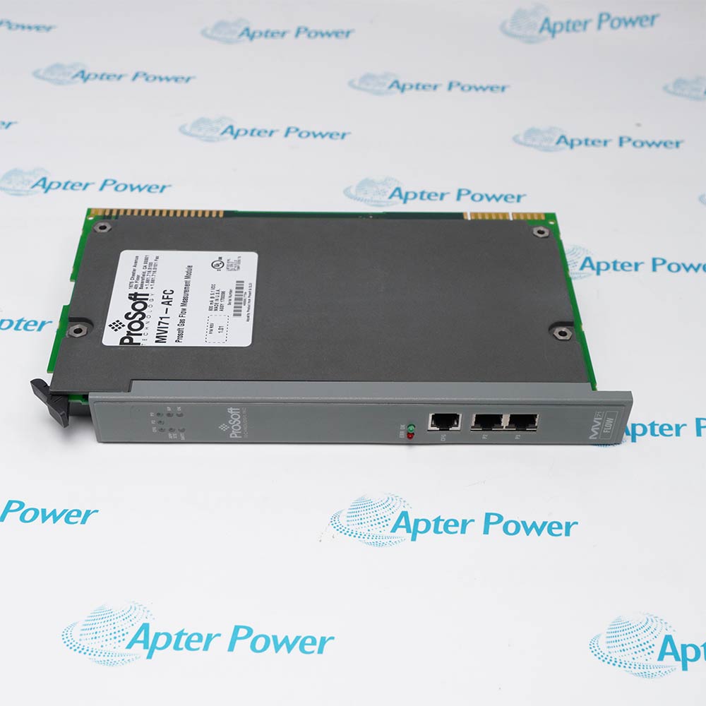
-
Match the complete marking
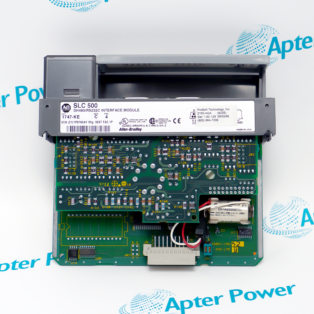
Include 2150-AGA 1747-KE and any revision or assembly number visible on the item. Keep the exact reference on your enquiry and quotation.
-
Check the offered item before ordering
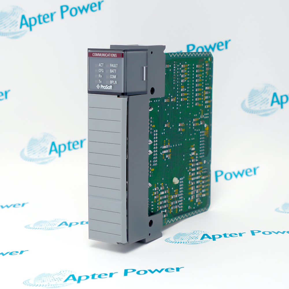
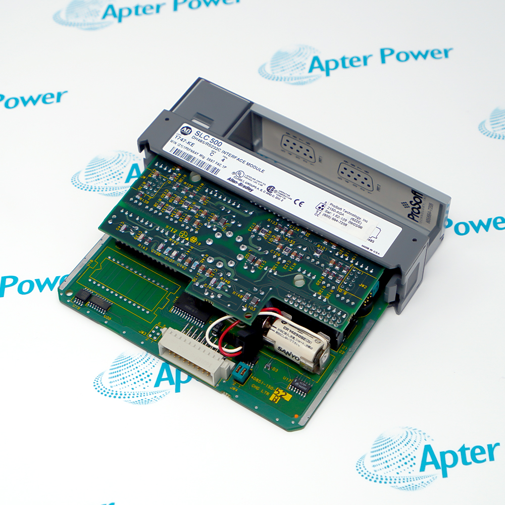
Request available label and connector photos. Have your maintenance team compare the offered 2150-AGA 1747-KE with the installed equipment and applicable ProSoft documentation.
Technical specifications for 2150-AGA 1747-KE
-
Manufacturer:ProSoft
-
Product Category:PLC Systems
-
Spare Part Number:2150-AGA 1747-KE
-
Weight:0.26 kg
-
Tariff Code:8537101190
-
Application label:2150-AGA (622E), as photographed
-
Base hardware marking:Allen-Bradley 1747-KE
-
Platform marking:SLC 500
-
Base hardware series:C, as photographed
-
Base FRN marking:4, as photographed; separate from ProSoft application firmware
-
Base interface designation:DH485/RS232C INTERFACE MODULE
-
Hardware-reference publication:1747-UM005B-EN-P, March 2006
-
Base power architecture:5 V DC and 24 V DC from the SLC backplane
-
Base serial interface selection:CONFIG and DF1 ports use hardware jumpers
-
Base DH-485 isolation:Non-isolated; assess the installed network coupling
-
Configuration retention hardware:Battery visible on the supplied assembly
-
Application software family:2150-AGA is included in the AFC turbine-flow software test scope
Information
- ProSoft 2150-AGA 1747-KE carries two distinct identities on the photographed assembly. Use the ProSoft application label together with the Allen-Bradley base-hardware marking when reviewing the installed SLC 500 system.
Base hardware: Allen-Bradley 1747-KE, Series C
Reference boundary: Base hardware and application firmware are separate
The standard 1747-KE design draws both 5 V DC and 24 V DC from the SLC backplane and provides CONFIG, DF1 and DH-485 interface positions. Its CONFIG and DF1 electrical modes are jumper selected; the DH-485 connection is non-isolated. These hardware relationships help identify the chassis and connector arrangement, while the ProSoft application determines the usable protocol behavior, controller data map and configuration procedure.
The manufacturer-hosted SIMT report 200303-3-601365 includes 2150-AGA within the AFC family covered by its turbine-flow calculation software assessment. That scope concerns calculation software accuracy, rather than the wiring or firmware identity of the photographed unit. Preserve the installed application program, calculation configuration and communication records together; a matching 1747-KE base label alone does not establish application equivalence.
-
ProSoft 2150-AGA 1747-KE base-hardware reference
Original Allen-Bradley base-hardware excerpt - PDF, 8 pages. 1747-KE identification, interfaces and hardware reference; ProSoft application procedures are separate. -
ProSoft 2150-AGA 1747-KE application review guide
Prepared by Apter Power - PDF, 4 pages. Dual-label identity, application preservation, base-hardware review and controlled replacement assessment.
Hardware-reference boundary: Allen-Bradley 1747-KE instructions describe the base module. Standard DF1 operation, configuration menus and replacement behavior must not be assumed for the ProSoft application.
-
SLC 500 application maintenance
Match both module identities and preserve the existing controller program, application revision and slot assignment. -
Flow-computation system review
Use the 2150-AGA application reference when reviewing an AFC installation; establish the actual calculation configuration from the installed project. -
Base-hardware identification
Compare the 1747-KE Series C label, board arrangement, connectors and jumper positions with the removed assembly. -
Controlled spare assessment
Keep application firmware and configuration evidence with the spare so hardware similarity is not mistaken for a validated replacement.
Record the ProSoft application label and the full Allen-Bradley base label. Do not substitute a standard 1747-KE solely because its housing matches.
Back up the installed controller program and application configuration before removal. Do not load standard 1747-KE firmware or reset defaults as a diagnostic shortcut.
Remove chassis power before inserting or removing the SLC module. Use the site isolation procedure for connected field circuits and process consequences.
Handle the assembly by its enclosure and use suitable ESD precautions. Protect the exposed board, memory components and connector contacts.
Photograph the existing jumper positions and cable labels before disconnection. Apply the ProSoft application procedure rather than assuming the standard 1747-KE mode settings.
The photographed assembly includes a battery. Establish the correct retention and service procedure before disconnecting it, then validate the complete application before release.
Alternative Names
Technical notes
Identity relationship: The supplied photograph shows ProSoft 2150-AGA (622E) on Allen-Bradley 1747-KE Series C hardware. Preserve the complete offered marking and separate the two revision identities.
Application boundary: 1747-UM005B-EN-P describes the Allen-Bradley base module. Its standard firmware operation and configuration procedures are not a substitute for the installed ProSoft application instructions.
Technical reference: Allen-Bradley DH-485/RS-232C Interface Module User Manual, 1747-UM005B-EN-P, March 2006; SIMT turbine-flow software test report 200303-3-601365. The test report scope is software calculation accuracy.

FAQ View All FAQ
-
Why does 2150-AGA 1747-KE carry two manufacturer labels?The supplied photograph shows a ProSoft 2150-AGA application label on an Allen-Bradley 1747-KE base module. Retain both identities because the application and base hardware describe different aspects of the assembly.
-
Does the FRN 4 label identify the ProSoft firmware in 2150-AGA 1747-KE?No. FRN 4 appears on the Allen-Bradley 1747-KE label. It must not be used as the ProSoft application firmware revision without matching application records.
-
Can a standard 1747-KE replace 2150-AGA 1747-KE directly?A matching base catalog number does not establish application equivalence. Compare the ProSoft firmware, controller data map, calculation settings and installed program before approving a replacement.
-
What power architecture does the base hardware of 2150-AGA 1747-KE use?The standard 1747-KE base design requires both 5 V DC and 24 V DC from the SLC backplane. Review the actual assembled-module load and any connected link-coupler supply when assessing the chassis power budget.
-
Are the base serial modes of 2150-AGA 1747-KE software-only settings?The 1747-KE base design uses hardware jumpers for CONFIG and DF1 electrical interface selection. Preserve the photographed installed positions and use the applicable ProSoft configuration procedure before changing them.
-
Is the DH-485 connection on the base hardware of 2150-AGA 1747-KE isolated?The standard 1747-KE DH-485 port is non-isolated. Assess the installed coupling, cable arrangement and grounding separately; this hardware reference does not establish the ProSoft application protocol.
-
What does the turbine-flow test reference establish for 2150-AGA 1747-KE?SIMT report 200303-3-601365 includes 2150-AGA in the AFC software family and limits its assessment to turbine-flow calculation software accuracy. It does not identify the firmware or wiring of the particular offered assembly.
-
Why should the battery on 2150-AGA 1747-KE remain connected during identification?The photographed board contains a battery, while the base-module design uses battery-backed configuration retention. Establish the applicable ProSoft retention procedure and secure the installed configuration before disconnecting or servicing it.
Supporting new and legacy automation
-
Please try to be as accurate as possible with your search.
-
We can quote you on 1000s of specialist parts, even if they are not listed on our website.
-
We can't find any results for “”.
You May Also Like
Product Browsing History
-
Whatsapp: +86 18030235313
Send us a message. -
sales13@apterpower.com
Complete our online form. -
+86 18030235313
Speak to our team in your native language.