-
Match the complete marking
Include COM-5 V2 and any revision or assembly number visible on the item. Keep the exact reference on your enquiry and quotation.
-
Check the offered item before ordering
Request available label and connector photos. Have your maintenance team compare the offered COM-5 V2 with the installed equipment and applicable PEACOCK documentation.
Technical specifications for COM-5 V2
-
Manufacturer:PEACOCK
-
Product Category:General Automation
-
Spare Part Number:COM-5 V2
-
Weight:1.46 kg
-
Tariff Code:8537101190
-
Product type:Digital comparator
-
Lower limit setting:Separate LOWER LIMIT thumbwheel control
-
Upper limit setting:Separate UPPER LIMIT thumbwheel control
-
Judgement indication:Three indicators: -NG / OK / +NG
-
Input marking:BCD IN
-
Input connector form:Multipin connector with retaining clips
-
Output marking:OUTPUT; round connector
-
Output legend A / B:A: +NG; B: COM
-
Output legend C / D:C: OK; D: -NG
Information
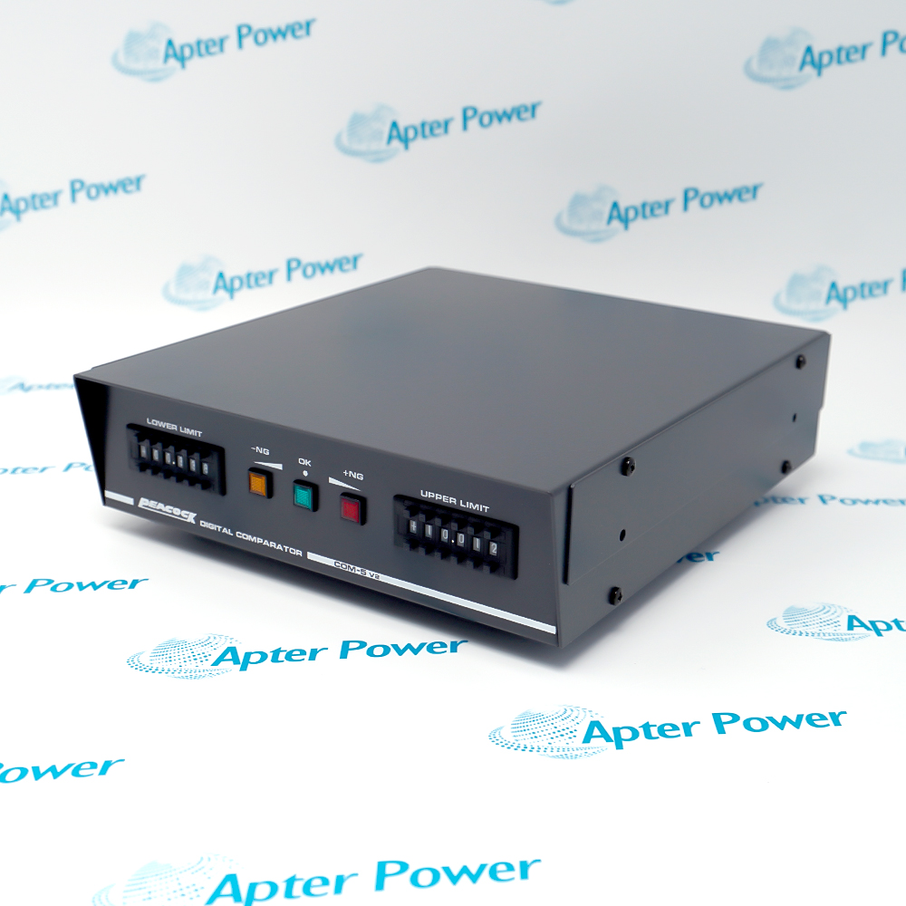
- PEACOCK COM-5 V2 provides a local comparison interface with separate limit settings and distinct -NG, OK and +NG indications for inspection work.
Limit controls: Separate LOWER LIMIT and UPPER LIMIT settings
Judgement indicators: -NG, OK and +NG
Rear interfaces: BCD IN and OUTPUT
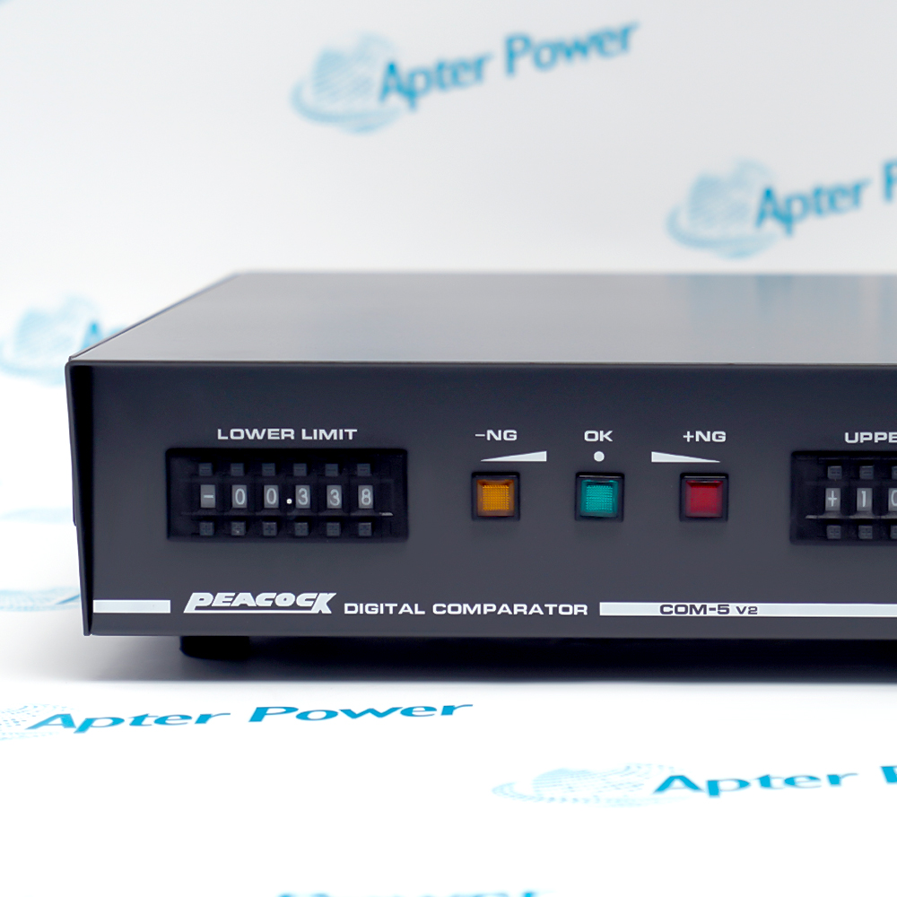
Three dedicated front indicators are marked -NG, OK and +NG. The lower and upper controls sit on either side of this judgement group, separating the limit settings from the displayed result. Record both signed settings before a change so that the approved inspection limits can be restored and checked.
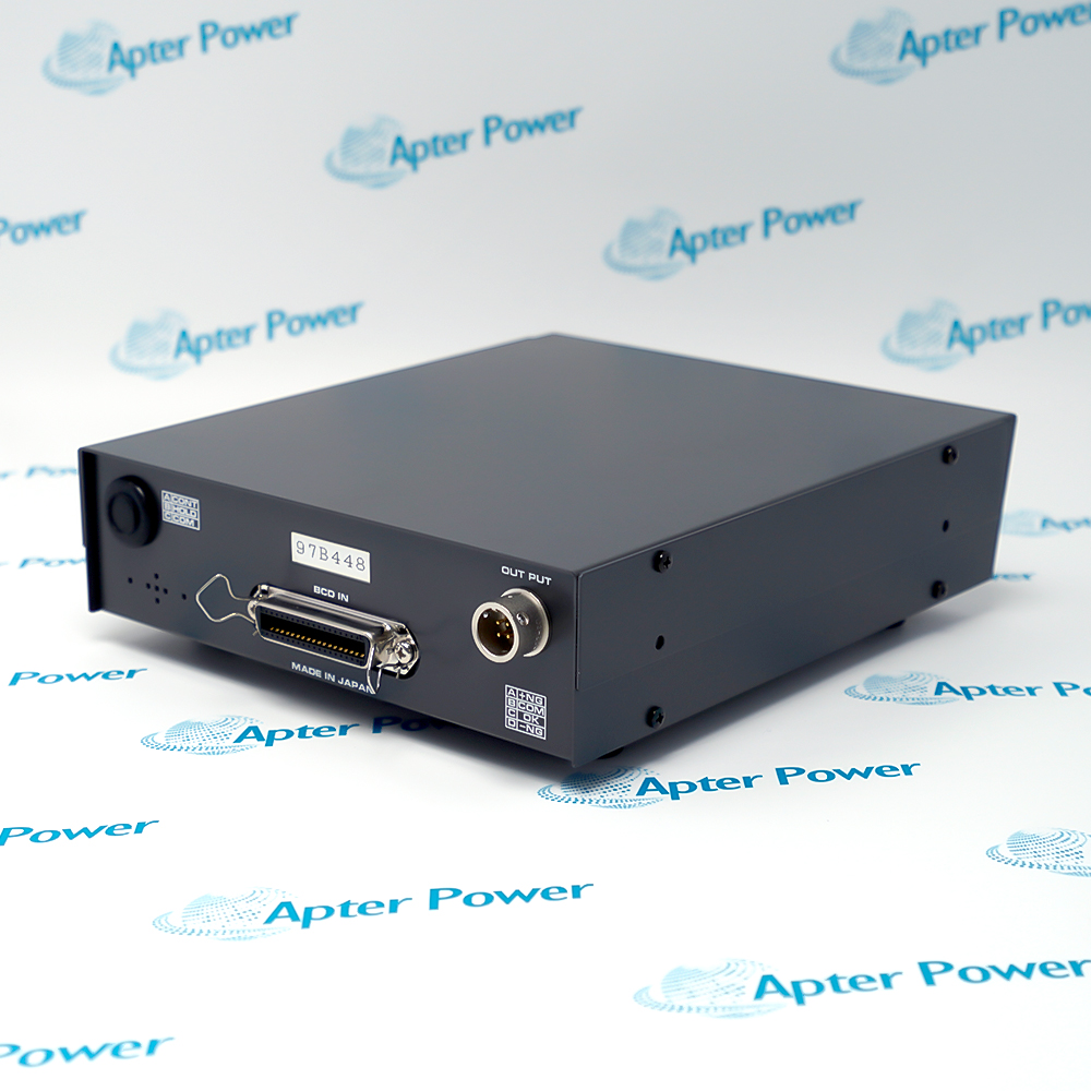
The rear panel separates a multipin BCD IN connection from a round OUTPUT connector. The output legend identifies A as +NG, B as COM, C as OK and D as -NG. Match these lettered markings to the installed mating connector and approved wiring drawing; the panel legend identifies signal roles rather than an electrical load rating.
-
PEACOCK COM-5 V2 technical reference
Apter Power technical reference - PDF, 5 pages, 25.1 KB. Complete V2 identity, limit controls, judgement indications, BCD input and output-label reference. -
PEACOCK COM-5 V2 installation planning guide
Apter Power installation planning guide - PDF, 5 pages, 25.4 KB. Instrument identification, limit-setting records, cable review and judgement-state acceptance planning.
Platform applications: The following applications describe digital comparator functions. Match the complete COM-5 V2 identity to the installed system before selecting a replacement.
-
Local limit comparison
Use the separate lower and upper controls to organize the approved limits for an inspection task. Preserve the signed settings when comparing an installed instrument with the offered COM-5 V2. -
Judgement indication
Read the three separately labelled -NG, OK and +NG indicators at the inspection station. Verify each required state through the approved test procedure before returning the station to use. -
BCD connection review
Identify the input cable at the rear BCD IN connector. Match its mating connector, wiring assignment and connected instrument to the installation drawing before replacement. -
Output signal identification
Use the rear A / B / C / D legend to distinguish +NG, common, OK and -NG roles. Review the receiving circuit separately before connecting the output cable.
Compare the full COM-5 V2 marking on the offered and installed units. Do not omit V2 from the equipment record or replacement enquiry.
Photograph and record the signed LOWER LIMIT and UPPER LIMIT settings before moving the instrument. Reapply only the limits approved for the inspection task.
Apply the site isolation procedure to the connected instrument and receiving circuits before disconnecting or reconnecting cables.
Match the BCD IN connector and cable against the actual installation drawing. Connector appearance alone does not establish the wiring assignment or compatible instrument.
Read A +NG, B COM, C OK and D -NG on the rear legend. Use the mating connector drawing for contact orientation; do not infer pin positions from a perspective photograph.
Use the approved inspection test method to check the required -NG, OK and +NG responses after installation. Record the final limit settings and receiving-circuit response before release.
Alternative Names
Technical notes
Installation relationship: Three dedicated front indicators are marked -NG, OK and +NG. The lower and upper controls sit on either side of this judgement group, separating the limit settings from the displayed result. Record both signed settings before a change so that the approved inspection limits can be restored and checked.
Configuration: The offered unit is COM-5 V2. Its front-panel limit controls and rear BCD IN and OUTPUT labels define the identification scope; match the complete instrument and installed wiring before replacement.
Technical reference: PEACOCK COM-5 V2 front-panel and rear-panel markings.

FAQ View All FAQ
-
How are the limit controls arranged on COM-5 V2?COM-5 V2 has separate LOWER LIMIT and UPPER LIMIT thumbwheel controls on the front panel. Record both signed settings when preparing an inspection setup or replacing the instrument.
-
Which judgement indications appear on COM-5 V2?Three dedicated indicators are marked -NG, OK and +NG. They provide distinct below-limit, accepted and above-limit judgement labels; validate the required responses with the approved inspection test procedure.
-
Where is the BCD input on COM-5 V2?The rear multipin connector is labelled BCD IN and has retaining clips. Match the input cable and its wiring assignment to the installed-system drawing before connecting it.
-
How is the output connection identified on COM-5 V2?The rear round connector is labelled OUTPUT. A separate lettered legend identifies its +NG, common, OK and -NG signal roles.
-
What does output terminal B mean on COM-5 V2?The rear-panel legend identifies B as COM, the common designation for the output connection. Preserve this assignment when reviewing the mating cable.
-
Which COM-5 V2 output markings identify the three judgement roles?The rear legend identifies A as +NG, C as OK and D as -NG. Match the connector letters to the approved wiring drawing; the perspective photograph is not a contact-orientation drawing.
-
What should be retained before changing COM-5 V2 limit settings?Record the complete COM-5 V2 identity and both signed front-panel settings. Associate the settings with the approved inspection task and verify the required judgement responses after the change.
-
What should be checked after reconnecting COM-5 V2?Confirm the BCD IN cable, OUTPUT cable and limit settings against the installation record. Use the approved test method to verify the required -NG, OK and +NG indications and the associated receiving-circuit response.
Supporting new and legacy automation
-
Please try to be as accurate as possible with your search.
-
We can quote you on 1000s of specialist parts, even if they are not listed on our website.
-
We can't find any results for “”.
You May Also Like
Product Browsing History
-
Whatsapp: +86 18030235313
Send us a message. -
sales13@apterpower.com
Complete our online form. -
+86 18030235313
Speak to our team in your native language.