Speak to a sourcing specialist
sales13@apterpower.com
Get a quick price for FBM201 P0914SQ
E-mail *
Mobile *
Company
Content *
Quantity *
Upload (gif, jpg, jpeg, png, bmp, doc, docx, xls, xlsx, ppt, pdf, csv)
For more information on how your data is processed and stored by Apterpower please read our privacy policy

What happens after you enquire

  • 1

    Requirement review

    We review the part number, quantity and delivery requirements and ask for any missing details.
  • 2

    Quotation and availability

    We confirm the proposed item, condition, availability, price and estimated lead time in the quotation.
  • 3

    Order confirmation and dispatch

    Once the quotation and purchasing details are agreed, your contact will coordinate the order and available dispatch information.

Technical specifications for FBM201 P0914SQ

  • Manufacturer:
    Invensys
  • Product Category:
    DCS Systems
  • Spare Part Number:
    FBM201 P0914SQ
  • Estimated shipping dimensions:
    4.5x11x11.5cm
  • Weight:
    0.3 kg
  • Tariff Code:
    8537101190
  • Counliy of origin:
    USA
  • Current inputs:
    8 isolated channels
  • Input span:
    0–20 mA DC
  • Nominal input impedance:
    61.5 Ω
  • Accuracy including linearity:
    ±0.03% of span
  • Accuracy temperature coefficient:
    ±50 ppm/°C
  • Loop compliance voltage:
    22.8 V DC
  • Input current limit:
    Less than 30 mA
  • A/D architecture:
    One sigma-delta converter per channel
  • Reading capability:
    One new reading every 25 ms
  • Common-mode rejection:
    >100 dB at 50/60 Hz
  • Normal-mode rejection:
    >95 dB at 50/60 Hz
  • Isolation test:
    600 V AC for 1 minute
  • Module Fieldbus rate:
    2 Mbps; redundant A/B paths
  • Power supply:
    24 V DC; +5%, -10%
  • Maximum power consumption:
    7 W
  • Maximum heat dissipation:
    3 W
  • Operating temperature:
    -20 to +70 °C, module
  • Storage temperature:
    -40 to +70 °C
  • Relative humidity:
    5–95%, noncondensing
  • Termination cable class:
    Type 1
  • Maximum TA cable length:
    30 m
  • Input connection:
    Two-wire DC per channel

Information

Overview Manuals Common Applications Product Precautions
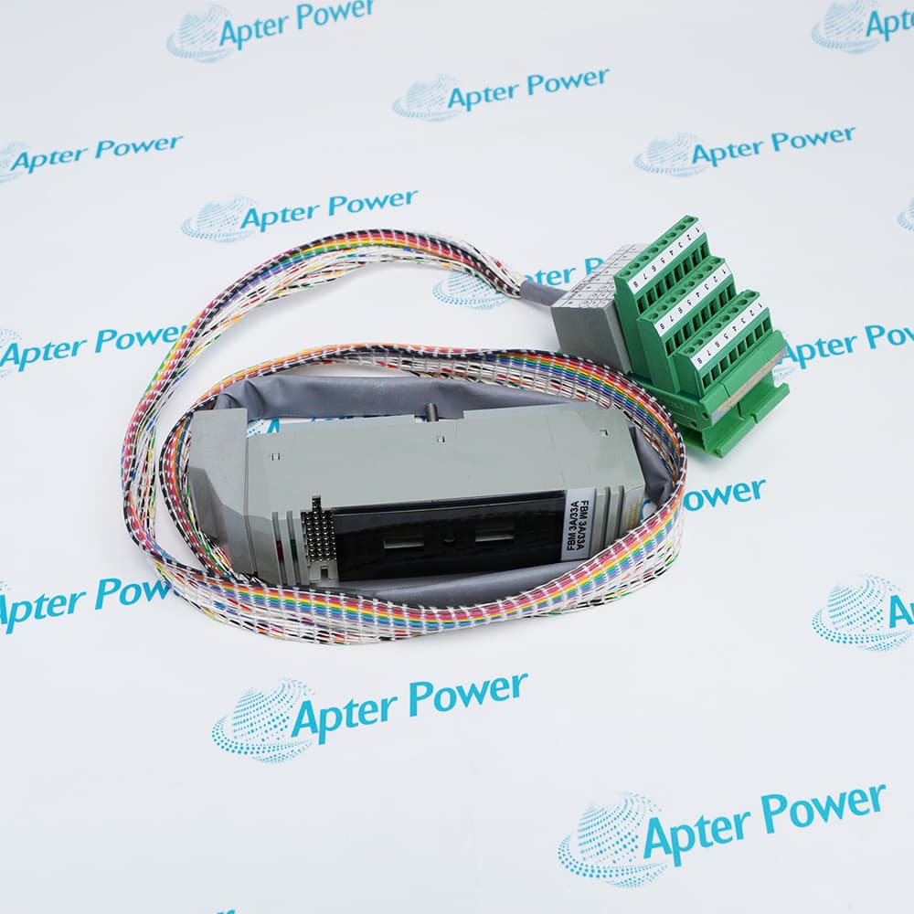
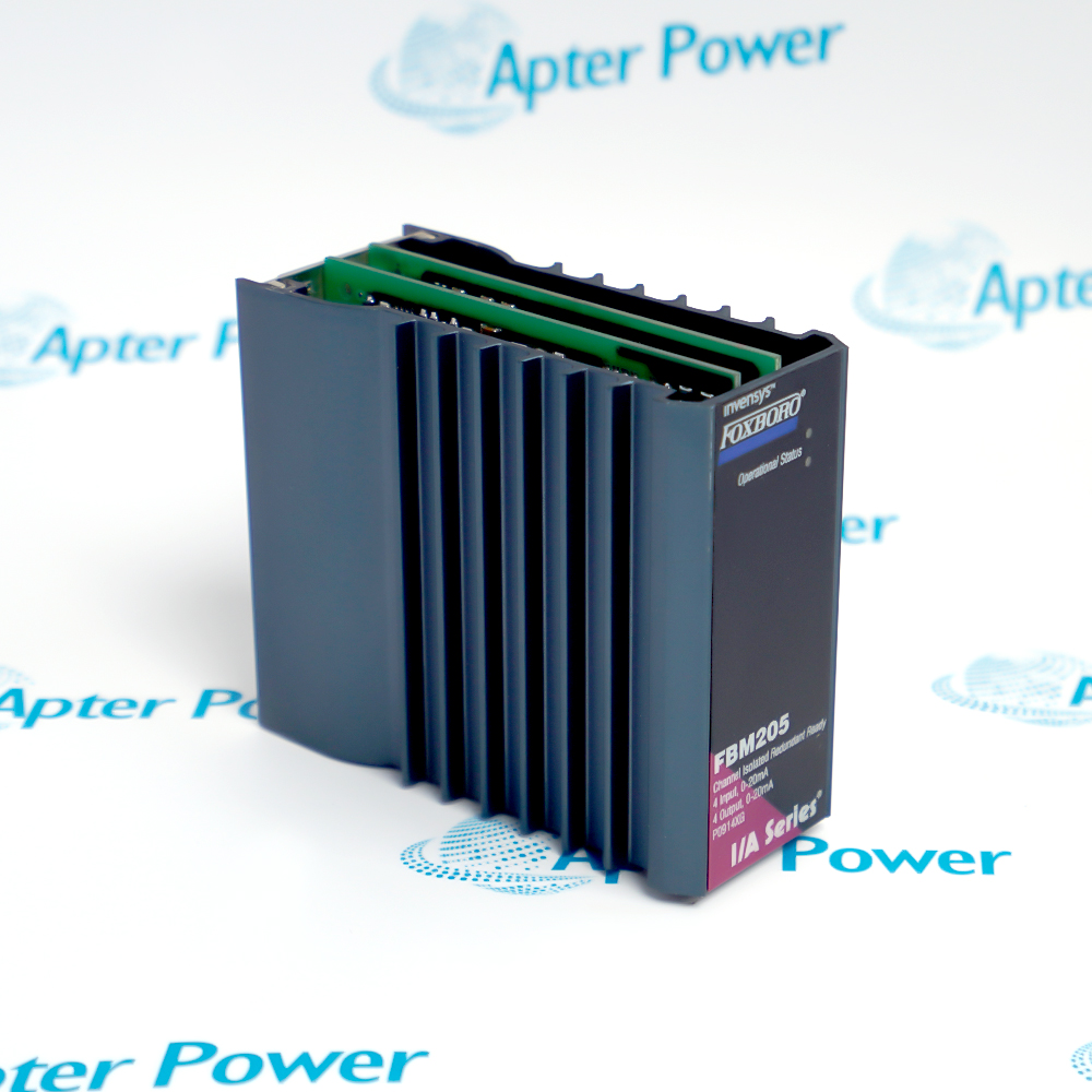
Foxboro FBM201 P0914SQ supports transmitter loops with internal or external loop power through the selected termination assembly, allowing the field-power arrangement to follow the instrumentation design.
  • Provides independent sigma-delta conversion on every measurement channel.
  • Offers software-adjustable integration and rate-of-change processing.
  • Accepts communications over either branch of the redundant module Fieldbus.
  • Allows module replacement while field termination cabling stays connected.

DIN-rail or rack-mounted baseplates carry the module connections. A removable Type 1 cable runs to the field termination assembly, separating the electronics location from the wiring termination point.

Important Notice: Check the actual transmitter voltage demand and total wiring resistance before setting the permitted loop length.

Foxboro FBM201 P0914SQ Manuals & Downloads
Foxboro FBM201 P0914SQ Manufacturer Technical Reference — Selected Pages (PDF)Foxboro FBM201 P0914SQ Installation & Commissioning Guide (PDF)

Review the input reference for current-loop and TA ratings. Use the commissioning guide to plan transmitter power, cable routing and current-injection checks.


Two-wire transmitter acquisition
Collect pressure, flow or other process measurements supplied as DC loop current.
Self-powered current sources
Bring an externally powered current signal into the controller through the appropriate termination.
Non-HART FBM01 modernization
Use the matching upgrade termination arrangement to transfer the analog input function.
Separated field marshalling
Route a removable termination cable between a baseplate and a dedicated DIN-rail wiring assembly.
Prepare the measurement circuits and termination arrangement before working on Foxboro FBM201 P0914SQ.
1
Treat this version as a current input; do not connect it as a direct voltage-input module.
2
Identify the loop-power source before connecting a transmitter.
3
Include transmitter voltage drop and conductor resistance in the compliance calculation.
4
Keep the current input within its measurement span during normal operation.
5
Distinguish channel current limiting from a permissible fault operating condition.
6
Select compression or ring-lug TA hardware to suit the existing conductors.
7
Use the appropriate Type 1 termination cable and preserve channel assignments.
8
Validate the intended non-HART device function when converting an FBM01 installation.

Technical notes

The 7 W maximum power requirement and the 3 W maximum heat dissipation describe different design budgets. Use the former when sizing the supply and the latter when assessing cabinet thermal loading.

FAQ View All FAQ

  • Can FBM201 P0914SQ directly accept the voltage ranges offered by FBM201b, FBM201c and FBM201d?
    No. FBM201 P0914SQ is the 0–20 mA DC version. The similarly named b, c and d variants are separate voltage-input modules.
  • How is the field-device cable distance determined for FBM201 P0914SQ?
    The distance depends on the 22.8 V DC compliance voltage, conductor resistance and voltage required by the field device. A cable-length choice must satisfy that complete loop-voltage budget.
  • What current-limiting behavior protects an FBM201 P0914SQ input?
    Each input is voltage regulated and current limited to less than 30 mA by design. A shorted current-limit circuit leaves approximately 100 mA as the fault limit; that value is not a normal operating setpoint.
  • Why are power consumption and heat dissipation different for FBM201 P0914SQ?
    The module has a maximum 7 W power requirement but a maximum 3 W heat dissipation. Supply capacity and enclosure cooling must therefore be assessed using their respective ratings.
  • Which legacy input function can FBM201 P0914SQ provide in a 100 Series upgrade?
    With the appropriate termination arrangement, it provides the FBM01 input function for non-HART devices. The upgrade uses the applicable termination assembly or termination-assembly adapter.
  • Are ring-lug terminations available for FBM201 P0914SQ current loops?
    Yes. P0916AB provides the PVC ring-lug arrangement and P0917JK the polyamide ring-lug arrangement. P0916AA and P0916XG provide the corresponding compression-terminal choices.
  • Does installing FBM201 P0914SQ require module or termination-assembly calibration?
    No calibration of the module or its termination assembly is required. Loop verification still checks the connected transmitter, channel assignment and application scaling.
  • Can externally powered transmitters be connected to FBM201 P0914SQ?
    Yes. Suitable termination assemblies support internally or externally loop-powered transmitters. The selected termination arrangement must agree with the power source used by each loop.
Related reading

Related cases and sourcing guidance

View all case studies
Manufacturers

Product Browsing History

Revisit the products you recently viewed on Apter Power.
SPEAK TO OUR TEAM
Let’s find the right solution for you.
Send us the part number, quantity and delivery destination. Our team will help confirm availability and lead time.
  • Whatsapp: +86 18030235313

    Send us a message.
  • sales13@apterpower.com

    Complete our online form.
  • +86 18030235313

    Speak to our team in your native language.