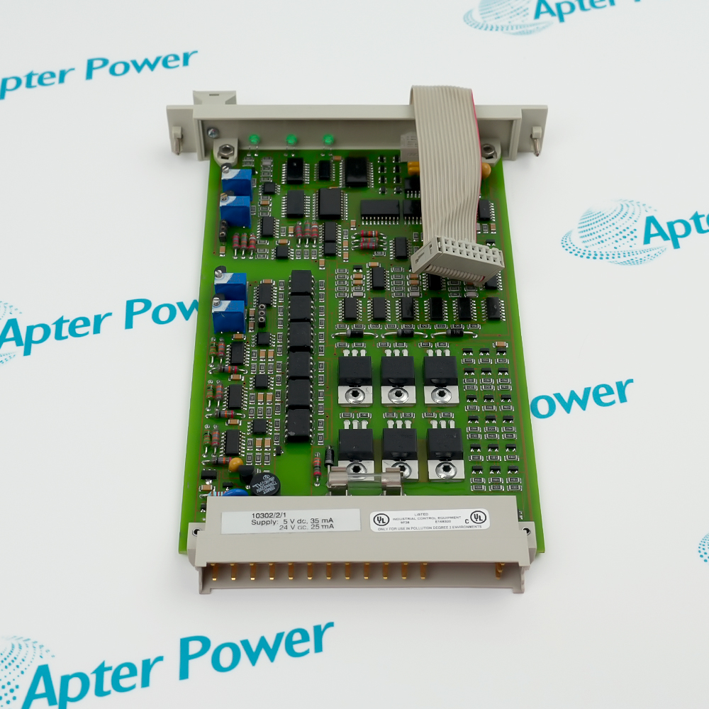
-
Match the complete marking
Include FTA-T-20 and any revision or assembly number visible on the item. Keep the exact reference on your enquiry and quotation.
-
Check the offered item before ordering
Request available label and connector photos. Have your maintenance team compare the offered FTA-T-20 with the installed equipment and applicable Honeywell documentation.
Technical specifications for FTA-T-20
-
Manufacturer:Honeywell
-
Product Category:DCS Systems
-
Spare Part Number:FTA-T-20
-
Weight:0.2 kg
-
Tariff Code:8537101190
-
Channels:8
-
Output function:Non-fail-safe relay contacts
-
Contact arrangement:Potential-free NO / NC changeover
-
Input voltage:24 Vdc nominal; 31 Vdc maximum
-
Cut-in voltage:19 Vdc
-
Relay input current:27 mA typical at 24 Vdc
-
Output current:5 A maximum at assembly level
-
Switching voltage:250 Vac / 300 Vdc maximum
-
Switching capacity:1250 VA; 150 W at 30 Vdc, subject to DC load curve
-
Protection:5 AT slow-blow fuse on each common contact
-
Indication:LED for each energized relay
-
Mounting:TS32 or TS35 DIN rail
Information
- Relay termination separates the FSC output command from the field contact circuit, with individual indication and fuse protection on FTA-T-20.
Field contacts: Potential-free NO and NC outputs
Connection: SIC input and screw-terminal field wiring
Each relay has an energization LED, and the common contact is protected by a 5 AT slow-blow fuse. The assembly output limit is 5 A, with maximum switching voltage of 250 Vac or 300 Vdc. Switching capacity is load-dependent: 1250 VA for AC and 150 W at 30 Vdc for the stated DC condition; the DC load curve must be respected.
A single SIC connector carries the system-side signals, while screw terminals provide field connections. The relay input is nominally 24 Vdc, with 19 Vdc cut-in and 31 Vdc maximum. Mounting uses a standard TS32 or TS35 DIN rail. Check the selected contact, fuse, connected load and coil-drive conditions before restoring the output circuit.
-
Honeywell FTA-T-20 technical reference
Original Honeywell excerpt - PDF, 5 pages, 159.4 KB. The listed values apply to the FTA-T-20 assembly. Component-level relay ratings do not override assembly limits; the connected FSC output and field load require separate matching. -
Honeywell FTA-T-20 installation planning guide
Prepared by Apter Power - PDF, 5 pages, 96.1 KB. Identity, configuration, connection and controlled acceptance planning.
Platform applications: The following applications describe FSC relay output functions. Match the complete FTA-T-20 identity to the installed system before selecting a replacement.
-
Relay isolation
Transfer FSC output commands to potential-free field contacts within the documented load limits. -
Changeover field circuits
Use the NO or NC connection appropriate to the designed field state and control narrative. -
Channel diagnostics
Compare each relay LED with commanded state and the observed field-circuit response. -
Termination maintenance
Maintain the SIC connection, screw terminals and individual common-contact fuses during controlled service.
Match FTA-T-20 and the installed output interface before disconnecting wiring.
Potential-free contacts may carry separately powered field circuits; isolate each applicable source.
Use the 5 A assembly limit and the AC or DC load conditions, including the DC switching curve.
Use the specified 5 AT slow-blow common-contact fuse; investigate a blown fuse before replacement.
Retain common, normally open and normally closed wiring and the required de-energized field state.
Test command, relay indication and field response under the approved commissioning procedure.
Alternative Names
Technical notes
Installation relationship: Each relay has an energization LED, and the common contact is protected by a 5 AT slow-blow fuse. The assembly output limit is 5 A, with maximum switching voltage of 250 Vac or 300 Vdc. Switching capacity is load-dependent: 1250 VA for AC and 150 W at 30 Vdc for the stated DC condition; the DC load curve must be respected.
Configuration: The listed values apply to the FTA-T-20 assembly. Component-level relay ratings do not override assembly limits; the connected FSC output and field load require separate matching.
Technical reference: Honeywell FSC Hardware Manual, FTA-T-20 data sheet version 1.2.

FAQ View All FAQ
-
How many output channels does FTA-T-20 provide?It provides eight relay channels with potential-free changeover contacts.
-
Are the outputs of FTA-T-20 fail-safe?The relay assembly is designated non-fail-safe. The complete application safety architecture must be assessed separately.
-
Which contact choices are available on FTA-T-20?Each channel provides normally open and normally closed connections around its common contact.
-
What relay input voltage applies to FTA-T-20?The nominal input is 24 Vdc, with a 19 Vdc cut-in threshold and 31 Vdc maximum.
-
What output-current limit applies to FTA-T-20?Use the assembly maximum of 5 A. A higher individual-relay component rating does not increase the assembly rating.
-
How are the contacts of FTA-T-20 protected?Each common contact uses a 5 AT slow-blow fuse. Select replacements to the original type and rating.
-
How does FTA-T-20 indicate relay state?Each energized relay has an LED. Confirm the actual field contact response as part of functional acceptance.
-
How is FTA-T-20 connected and mounted?System signals enter through one SIC connector, field wiring uses screw terminals, and the assembly mounts on a TS32 or TS35 DIN rail.
Supporting new and legacy automation
-
Please try to be as accurate as possible with your search.
-
We can quote you on 1000s of specialist parts, even if they are not listed on our website.
-
We can't find any results for “”.
You May Also Like
Product Browsing History
-
Whatsapp: +86 18030235313
Send us a message. -
sales13@apterpower.com
Complete our online form. -
+86 18030235313
Speak to our team in your native language.