Speak to a sourcing specialist
sales13@apterpower.com
Get a quick price for 10014/F/F
E-mail *
Mobile *
Company
Content *
Quantity *
Upload (gif, jpg, jpeg, png, bmp, doc, docx, xls, xlsx, ppt, pdf, csv)
For more information on how your data is processed and stored by Apterpower please read our privacy policy

What happens after you enquire

  • 1

    Requirement review

    We review the part number, quantity and delivery requirements and ask for any missing details.
  • 2

    Quotation and availability

    We confirm the proposed item, condition, availability, price and estimated lead time in the quotation.
  • 3

    Order confirmation and dispatch

    Once the quotation and purchasing details are agreed, your contact will coordinate the order and available dispatch information.

Technical specifications for 10014/F/F

  • Manufacturer:
    Honeywell
  • Product Category:
    DCS Systems
  • Spare Part Number:
    10014/F/F
  • Estimated shipping dimensions:
    4x18.5x12.8cm
  • Weight:
    0.35 kg
  • Tariff Code:
    8537101190
  • Counliy of origin:
    USA
  • Interface channels:
    2
  • Electrical interface:
    RS-232
  • Output state:
    Tri-state
  • Program storage:
    FLASH

Information

Overview Manuals Common Applications Product Precautions
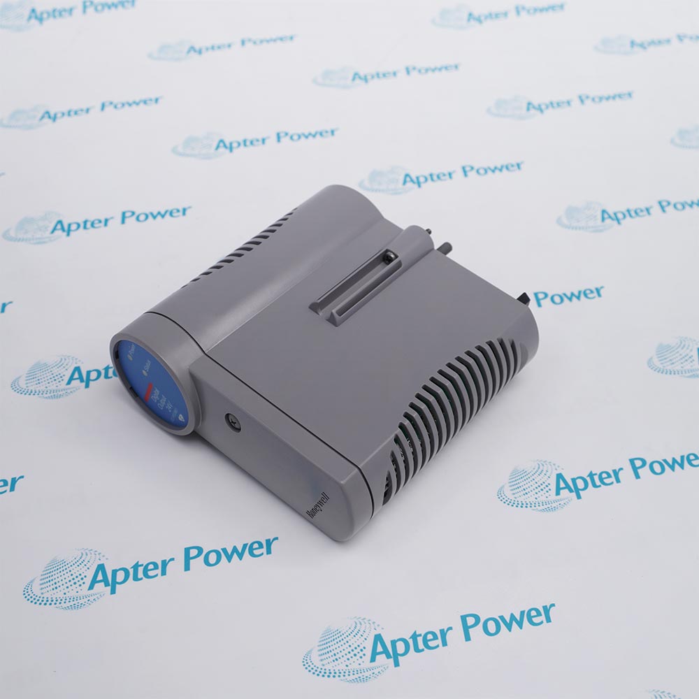
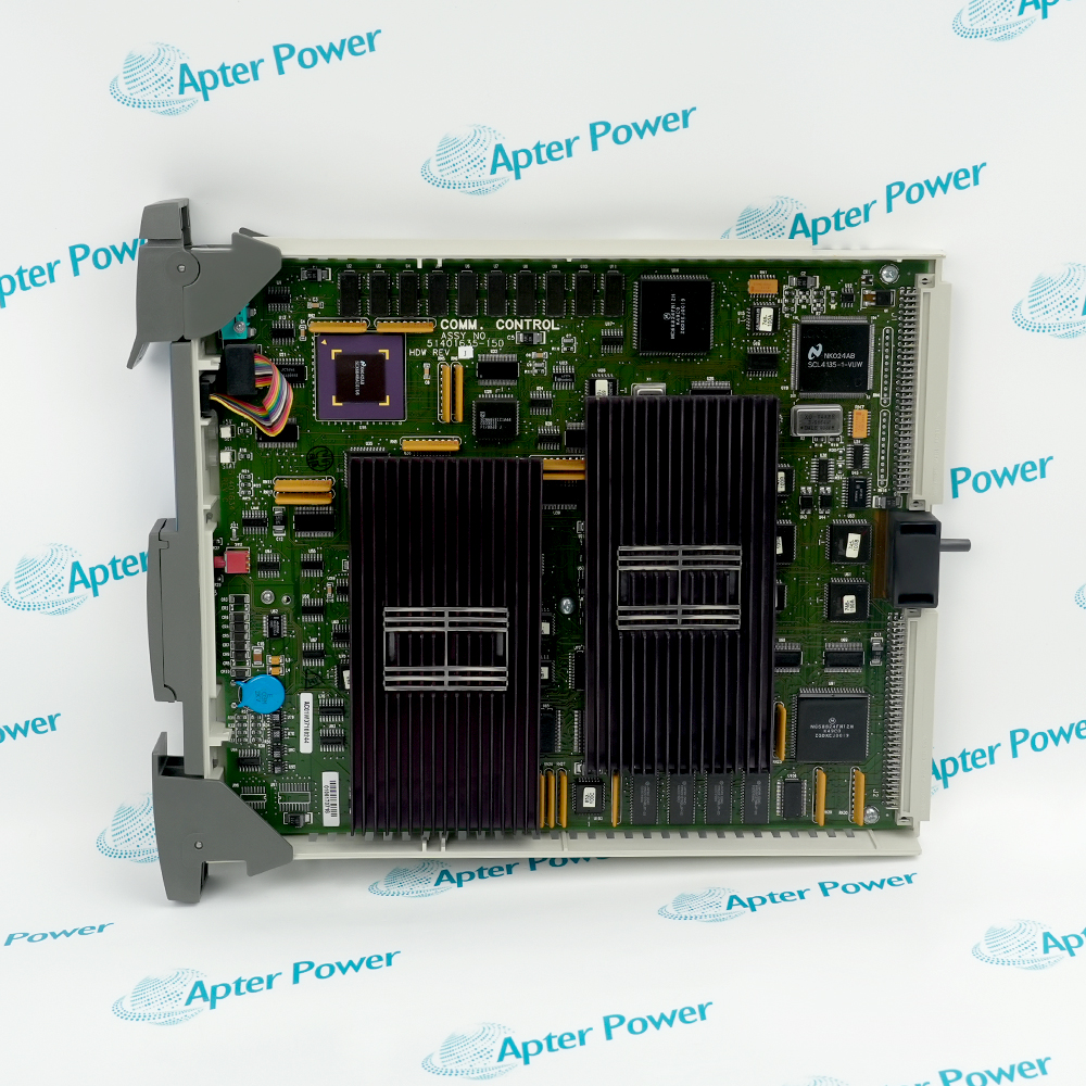
Honeywell 10014/F/F is a Fail Safe Controller communication module with two tri-state RS-232 interfaces. It exchanges serial data between the FSC Central Part and connected equipment.
  • Provides two independently assigned serial communication channels
  • Uses tri-state RS-232 outputs for controlled line sharing
  • Links the FSC Central Part with configured external serial equipment
  • Retains its communication application in FLASH program storage

10014/F/F is installed with the FSC Central Part, two identified RS-232 serial cables, configured peer devices and the FSC communication application.

Typical engineered duties include safety-system serial gateways, package-unit data exchange, FSC maintenance communication and legacy serial-device integration.

Important Notice: Confirm the complete 10014/F/F marking, both port assignments, cable identity, peer-device serial settings and FLASH program revision before controlled commissioning or replacement.


Apter Power 10014/F/F Manuals and Guides
Apter Power 10014/F/F Product Technical Reference PDFApter Power 10014/F/F Installation and Verification PDF
The first document is a model-specific technical reference. The second provides a separate installation, channel-assignment, commissioning and return-to-service workflow.
10014/F/F safety-system serial gatewaysExchanges configured serial data between the FSC Central Part and an external gateway device.
10014/F/F package-unit data exchangeConnects a packaged machine or subsystem through one of the documented RS-232 channels.
10014/F/F maintenance communicationSupports the assigned FSC serial maintenance path while preserving both channel identities.
10014/F/F legacy serial integrationMaintains controlled RS-232 communication with installed equipment during system service or migration.
Read the applicable Honeywell Fail Safe Controller instructions before work. Verify 10014/F/F, its FLASH application and both installed RS-232 channel assignments.
1Match the complete 10014/F/F marking to the assigned FSC Central Part position.
2Isolate the controller-side and peer-device energy before disconnecting either serial cable.
3Protect the module connectors and electronic assembly with approved ESD controls.
4Record both RS-232 cable tags, port assignments and configured peer devices before removal.
5Retain the installed serial settings and FLASH program revision in the maintenance record.
6Restore one channel at a time and check controlled receive and transmit operation.
7Complete a documented functional test for the assigned serial gateway duty before release.

Technical notes

Record both port assignments and serial settings, isolate connected equipment and verify controlled receive/transmit operation on each channel after installation.

FAQ View All FAQ

  • What evidence should be retained after 10014/F/F returns to service?
    Retain the full model identity, as-left connections, configuration, diagnostic result and the final controlled test record for safety-system serial gateways.
  • How is 10014/F/F identified before installation in a Fail Safe Controller cabinet?
    Match the full 10014/F/F marking and part number 10014/F/F to the assigned position and installed FSC Central Part.
  • Which companion hardware must be checked when replacing 10014/F/F?
    Verify FSC Central Part, two RS-232 serial cables and configured peer devices against the approved cabinet and project record before fitting the Dual RS-232 Communication Module.
  • What wiring information should be recorded before removing 10014/F/F?
    Record terminal identifiers, shields, cable tags and the as-found channel or port assignment for 10014/F/F.
  • How should engineers validate 10014/F/F after configuration?
    Restore the documented Fail Safe Controller assignment, review diagnostics and run a controlled test of both serial communication channels.
  • Can 10014/F/F be moved to a different slot or duty without review?
    No. Confirm keying, companion hardware and the approved configuration before assigning 10014/F/F to another position or function.
  • Which technical value is especially important during 10014/F/F commissioning?
    Verify program storage is FLASH and use the manufacturer procedure for the controlled functional test.
  • What should be checked if 10014/F/F does not support package-unit data exchange after installation?
    Check seating, both RS-232 serial cables, configured peer devices, field energy and model-specific diagnostics before replacing additional hardware.
Related reading

Related cases and sourcing guidance

View all case studies