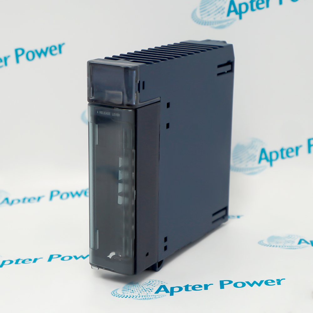
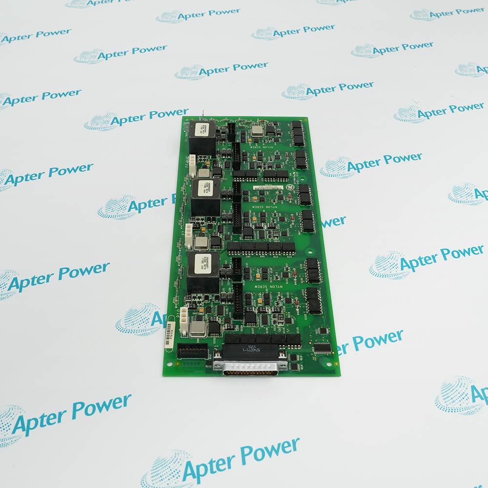
GE/Emerson IC200UDR005 is a 28-point VersaMax Micro programmable logic controller with an integrated CPU and I/O and a 120/240 V AC power supply.
- Sixteen 24 V DC positive- or negative-logic inputs
- One configurable 24 V DC output and eleven normally open Form A relay outputs
- High-speed counters to 10 kHz and Q1 pulse-train or PWM output to 5 kHz
- RS-232 and RS-485 serial ports with support for up to four expansion units
It reads discrete and pulse signals, executes the configured control logic, drives solid-state and relay loads, and exchanges programming or serial data for compact packaging, dispensing, motion-counting, material-handling and process-control equipment.
Important Notice: Official sources identify base catalog number IC200UDR005 but do not define the requested DJ suffix, which must be confirmed on the exact manufacturer's nameplate.
Apter Power IC200UDR005-DJ Manuals and Guides
Important Notice: The first link is the product-parameters PDF prepared only from the cited manufacturer information; the second link is the Apter Power product manual. Confirm the physical nameplate, current manufacturer documents, and host-system requirements before installation or replacement.
Packaging and interlock control
Uses integrated discrete inputs and outputs for compact machine sequences and interlocks.
Meter and flow pulse counting
Selected inputs process documented high-speed counter signals up to 10 kHz.
Motion-related counting
Combines counter inputs with the Q1 counter, pulse-train or PWM output where configured.
Material-handling and process equipment
Provides standalone control or adds up to four VersaMax Micro expansion units when required.
Follow GFK-1645M and applicable electrical regulations, and verify the exact unit label before installation or programming.
1
Turn off PLC power before removing a terminal assembly or attached field wiring.
2
Use only the published AC input range and frequency because this model is not a 24 V DC-powered PLC.
3
Do not exceed the 200 mA maximum built-in +24 V DC supply available for input circuits and user devices.
4
Provide an external AC or DC source for field devices connected to the relay outputs.
5
Do not use relay outputs for pulse-train or PWM signals because only Q1 supports those functions.


 Videos
 News
News Applications