Speak to a sourcing specialist
sales13@apterpower.com
Get a quick price for DS200KLDCG1AAA
E-mail *
Mobile *
Company
Content *
Quantity *
Upload (gif, jpg, jpeg, png, bmp, doc, docx, xls, xlsx, ppt, pdf, csv)
For more information on how your data is processed and stored by Apterpower please read our privacy policy

What happens after you enquire

  • 1

    Requirement review

    We review the part number, quantity and delivery requirements and ask for any missing details.
  • 2

    Quotation and availability

    We confirm the proposed item, condition, availability, price and estimated lead time in the quotation.
  • 3

    Order confirmation and dispatch

    Once the quotation and purchasing details are agreed, your contact will coordinate the order and available dispatch information.

Technical specifications for DS200KLDCG1AAA

  • Manufacturer:
    General Electric
  • Product Category:
    Gas Turbine Control
  • Spare Part Number:
    DS200KLDCG1AAA
  • Estimated shipping dimensions:
    28x21.9x2.2cm
  • Weight:
    0.54 kg
  • Tariff Code:
    8537101190
  • Counliy of origin:
    USA
  • Product family:
    Mark V
  • Board function:
    Key/LED/display board
  • Functional acronym:
    KLDC
  • Assembly type:
    Normal assembly
  • PCB coating:
    Normal coating
  • Revision identity:
    AAA
  • LED count:
    32; DS1 to DS32
  • Display count:
    21 four-character displays
  • Jumper count:
    1
  • Rear connector:
    40-pin connection strip
  • L1 connection:
    2 wires

Information

Overview Manuals Common Applications Product Precautions
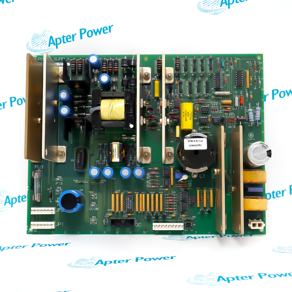
GE DS200KLDCG1AAA retains the KLDC functional identity and the complete AAA revision string. Replacement work depends on preserving the rear 40-pin connection, L1 wiring, jumper position and mechanical mounting record.
  • Mark V KLDC interface board
  • 32 LEDs identified DS1 through DS32
  • Twenty-one 4-character displays
  • One jumper and one rear 40-pin connection strip

The controlled system path is Mark V control data → DS200KLDCG1AAA key/display logic → LED and four-character display elements → Local operator status and input. Verify each boundary against the installed project record.

Important Notice: De-energize the Mark V cabinet and verify stored-energy conditions before handling DS200KLDCG1AAA.

GE DS200KLDCG1AAA Manuals & Downloads
GE DS200KLDCG1AAA Technical Reference (PDF)GE DS200KLDCG1AAA Installation & Commissioning Guide (PDF)

The Technical Reference consolidates the verified data available for GE DS200KLDCG1AAA; the Installation & Commissioning Guide organizes controlled field preparation, checks and acceptance.


Local Mark V status display
Shows configured operating states through the LED and character-display field.
Operator key input
Carries local key commands through the installed KLDC interface path.
Maintenance indication
Lets technicians compare DS1-DS32 patterns with the controlled system record.
Exact-board replacement
Restores the same KLDC position while preserving the AAA revision, jumper and cable mapping.
Apply these controls to GE DS200KLDCG1AAA before isolation, removal, reconnection, energization and release.
1
De-energize the Mark V cabinet and verify stored-energy conditions before handling DS200KLDCG1AAA.
2
Record the complete AAA suffix, installed position and all mounting hardware before removal.
3
Photograph the 40-pin connection strip, L1 wiring and cable routing before disconnection.
4
Capture the single jumper position and do not change it without the controlled board documentation.
5
Use ESD controls and avoid touching display, key and connector contacts.
6
Maintain the original cable route so signal wiring remains separated from high-voltage conductors and airflow paths remain clear.
7
After installation, inspect every DS1-DS32 LED position and all twenty-one four-character displays for complete operation.
8
Verify every permitted key input and the resulting Mark V response before returning the operator interface to service.

Technical notes

GE DS200KLDCG1AAA is a Mark V key, LED and display board with thirty-two indicators, twenty-one four-character displays and a rear 40-pin connection strip.

FAQ View All FAQ

  • What is the function of GE DS200KLDCG1AAA?
    It is the Mark V key, LED and display board identified by the KLDC functional acronym.
  • How many LEDs are fitted to GE DS200KLDCG1AAA?
    The board has thirty-two LEDs identified DS1 through DS32.
  • What display arrangement is documented for GE DS200KLDCG1AAA?
    It carries twenty-one four-character display elements.
  • Which rear connector is used by GE DS200KLDCG1AAA?
    One 40-pin connection strip is located at the rear of the board.
  • How many jumpers are recorded on GE DS200KLDCG1AAA?
    The exact-model hardware record identifies one jumper.
  • Which auxiliary wiring is associated with GE DS200KLDCG1AAA L1?
    Two wires connect at the L1 point and must be restored to the same recorded positions.
  • What does the AAA suffix identify on GE DS200KLDCG1AAA?
    AAA is retained as the board's complete revision identity; it must be matched without shortening the model.
  • Which checks finish GE DS200KLDCG1AAA commissioning?
    Confirm cable and jumper match, then test all LEDs, all character displays, permitted key inputs and the corresponding Mark V responses.
Manufacturers

Product Browsing History

Revisit the products you recently viewed on Apter Power.
SPEAK TO OUR TEAM
Let’s find the right solution for you.
Send us the part number, quantity and delivery destination. Our team will help confirm availability and lead time.
  • Whatsapp: +86 18030235313

    Send us a message.
  • sales13@apterpower.com

    Complete our online form.
  • +86 18030235313

    Speak to our team in your native language.