Speak to a sourcing specialist
sales13@apterpower.com
Get a quick price for 9200-06-05-05-00
E-mail *
Mobile *
Company
Content *
Quantity *
Upload (gif, jpg, jpeg, png, bmp, doc, docx, xls, xlsx, ppt, pdf, csv)
For more information on how your data is processed and stored by Apterpower please read our privacy policy

What happens after you enquire

  • 1

    Requirement review

    We review the part number, quantity and delivery requirements and ask for any missing details.
  • 2

    Quotation and availability

    We confirm the proposed item, condition, availability, price and estimated lead time in the quotation.
  • 3

    Order confirmation and dispatch

    Once the quotation and purchasing details are agreed, your contact will coordinate the order and available dispatch information.

Technical specifications for 9200-06-05-05-00

  • Manufacturer:
    Bently Nevada
  • Product Category:
    Machinery Monitoring Systems
  • Spare Part Number:
    9200-06-05-05-00
  • Estimated shipping dimensions:
    10.2x4x4cm
  • Weight:
    0.42 kg
  • Tariff Code:
    8537101190
  • Counliy of origin:
    USA
  • Transducer family:
    9200 Seismoprobe
  • Measurement:
    Absolute vibration velocity
  • Mounting angle / minimum frequency:
    0° ±100° / 10 Hz
  • Connection:
    Terminal-block top mount
  • Mounting base:
    No base; 1/2-20 UNF-3A stud
  • Approval option:
    No approvals
  • Signal type:
    Self-generating two-wire velocity output

Information

Overview Manuals Common Applications Product Precautions
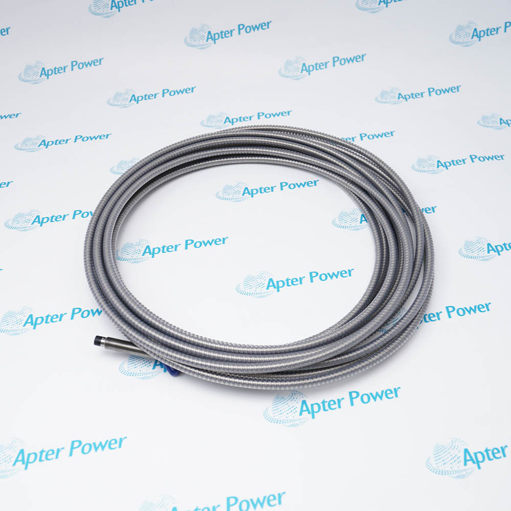
Bently Nevada 9200-06-05-05-00 measures absolute casing or bearing-housing vibration through a two-wire electromagnetic velocity element.
  • Measures casing vibration relative to free space.
  • Uses the vertical 10 Hz minimum-frequency execution.
  • Provides a terminal-block top connection.
  • Mounts through the 1/2-20 UNF-3A stud without a separate base.

The transducer is installed on a rigid bearing housing or machine casing so that the selected axis represents the vibration direction of interest. Mounting stiffness and cable routing directly affect the usable signal.

Important Notice: Confirm the complete 9200-06-05-05-00 mounting-angle, connector and base options. Verify low-frequency response, noise floor and monitor scaling before service release.

Bently Nevada 9200-06-05-05-00 Manuals & Downloads
Bently Nevada 9200-06-05-05-00 Official Technical Reference Excerpt (PDF)Bently Nevada 9200-06-05-05-00 Installation & Commissioning Guide (PDF)

The first document covers the product function, system role and technical selection. The installation guide covers identification, connection checks, commissioning and the acceptance record.


Bearing-housing vibration
Measures absolute motion on rolling-element bearing housings.
Machine-casing monitoring
Feeds a velocity channel for fans, pumps, motors and similar machines.
Periodic diagnostic measurements
Connects to suitable test or diagnostic instruments for velocity observation.
Continuous monitoring input
Provides a two-wire signal to a compatible vibration monitor.
Before installing Bently Nevada 9200-06-05-05-00, confirm the documented system, interfaces and controlled configuration.
1
Confirm the complete 9200-06-05-05-00 mounting-angle, connector and base options.
2
Prepare a flat, rigid mounting surface aligned with the measurement axis.
3
Use the specified 1/2-20 UNF-3A stud and prevent rocking at the mounting interface.
4
Protect the terminal-block wiring inside a suitable enclosure or conduit system.
5
Keep signal cable away from high-noise power conductors and provide the required shield treatment.
6
Do not apply an isolated-base installation rule to this no-base execution.
7
Check polarity and phase convention before comparing the channel with previous data.
8
Verify low-frequency response, noise floor and monitor scaling before service release.

Technical notes

Confirm the complete 9200-06-05-05-00 mounting-angle, connector and base options. Verify low-frequency response, noise floor and monitor scaling before service release.

FAQ View All FAQ

  • Which vibration quantity is sensed by 9200-06-05-05-00?
    It measures absolute vibration velocity of the mounting surface.
  • What orientation range is selected in 9200-06-05-05-00?
    Option 06 is the 0° ±100° execution with a 10 Hz minimum operating frequency.
  • How is field wiring connected to 9200-06-05-05-00?
    Option 05 uses the terminal-block top-mount connection.
  • Which mechanical base is selected for 9200-06-05-05-00?
    The second 05 selects no base and a 1/2-20 UNF-3A mounting stud.
  • Does the final 00 add hazardous-area approval to 9200-06-05-05-00?
    No. The approval option is none.
  • Why must the mounting surface be rigid for 9200-06-05-05-00?
    A flexible or rocking mount attenuates and distorts the casing-velocity signal.
  • Which polarity check is needed after wiring 9200-06-05-05-00?
    Confirm that the measured phase and direction follow the plant convention for the selected axis.
  • What commissioning test is most useful for 9200-06-05-05-00?
    Compare the stationary noise floor and a controlled vibration response with the configured velocity scale.
SPEAK TO OUR TEAM
Let’s find the right solution for you.
Send us the part number, quantity and delivery destination. Our team will help confirm availability and lead time.
  • Whatsapp: +86 18030235313

    Send us a message.
  • sales13@apterpower.com

    Complete our online form.
  • +86 18030235313

    Speak to our team in your native language.