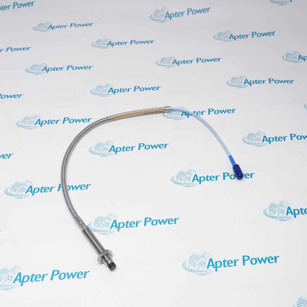
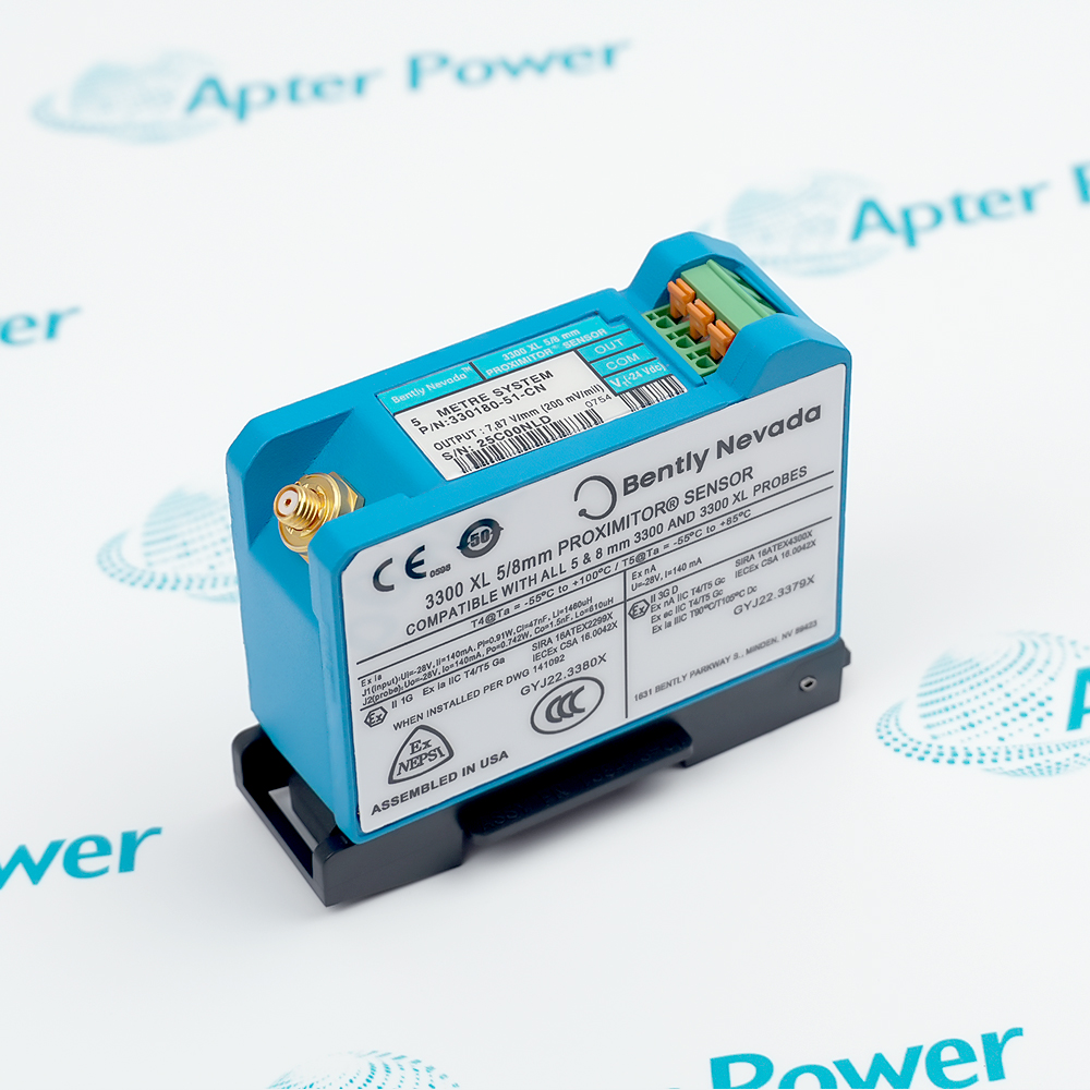
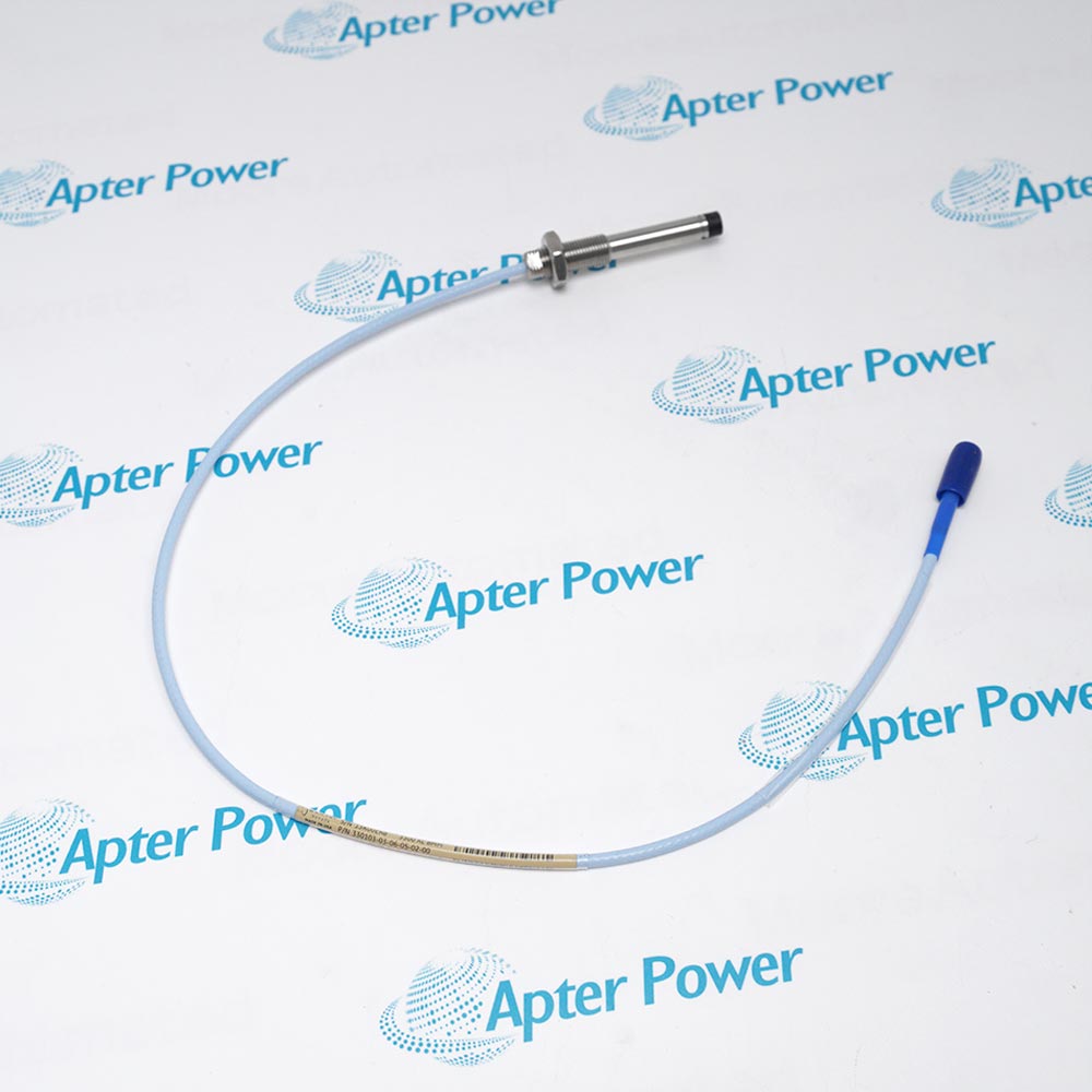
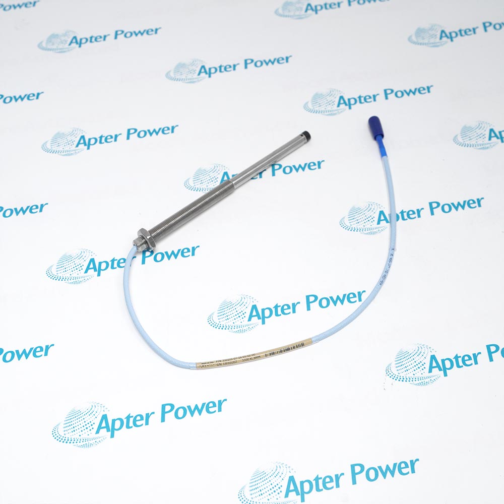
Product image is representative; revision or series may vary. Contact us to request a specific version.
Product Describe:
Bently Nevada 330750-40 is a High-Temperature Velomitor sensor system with a four-metre integral cable between the sensing head and remote electronics.
Its separated sensing head and electronics arrangement supports velocity measurement where the machine surface is hotter than standard sensor electronics can tolerate.
Separates the sensing head from its electronic conditioning section.
Uses a four-metre integral high-temperature cable.
Produces a velocity-proportional output for casing vibration.
Supports long field-cable runs to compatible monitoring equipment.
Use 330750-40 only in the specified monitoring chain and verify the complete signal path after controlled replacement.
Important Notice: Capture the installed 330750-40 interfaces and configuration before removal, then prove the monitored value, status and alarm path after installation.
The first PDF covers the product function, system role and technical selection. The installation guide covers identification, connection checks, commissioning and the acceptance test results.

Gas turbine casing
Measures velocity on high-temperature housings.
Steam turbine bearing housing
Monitors casing vibration near hot surfaces.
Exhaust equipment
Places electronics away from elevated temperatures.
Machine protection retrofit
Restores a specified high-temperature velocity channel.
Before installing Bently Nevada 330750-40, confirm the specified system, interfaces and controlled configuration.
1
Confirm the complete 330750-40 marking and the specified high-temperature velomitor sensor system position.
2
Place the affected machine protection channel in the approved maintenance state.
3
Capture the installed sensor family, integral cable length and sensitivity before removal.
4
De-energize the associated monitor, sensor supply or field circuit as the procedure requires.
5
Label every connector, conductor and shield before separation.
6
Inspect mating contacts, mounting hardware and cable condition before installation.
7
Restore the retained configuration and verify signal polarity and proportional response.
8
Function-test the complete alarm, indication and shutdown path before returning the machine to service.
Technical notes
Capture the installed 330750-40 interfaces and configuration before removal, then prove the monitored value, status and alarm path after installation.