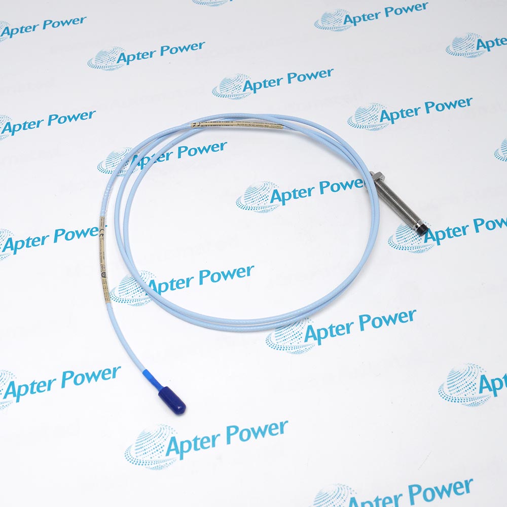
Technical specifications for 330101-00-13-10-02-00
-
Manufacturer:Bently Nevada
-
Product Category:Machinery Monitoring Systems
-
Spare Part Number:330101-00-13-10-02-00
-
Estimated shipping dimensions:1.6x1.4x112cm
-
Weight:0.06 kg
-
Tariff Code:8537101190
-
Counliy of origin:USA
-
Probe Family:3300 XL 8 mm
-
Mounting Thread:3/8-24 UNF
-
Armor Execution:Without armor
-
Unthreaded Length Option:AA00 = 0.0 in
-
Overall Case Length Option:BB13 = 1.3 in
-
Total Probe Length:CC10 = 1.0 m
-
Connector and Cable:DD02 = miniature coaxial ClickLoc, standard cable
-
Included Connector Protector:Not selected by DD02
-
Approval Selection:EE00 = not required
-
Nominal Probe DC Resistance:7.59 +/-0.50 ohm; center to outer conductor
-
Standard Probe Cable:75 ohm triaxial; FEP insulated
-
Probe Tip Material:Polyphenylene sulfide (PPS)
-
Probe Case Material:AISI 303 or 304 stainless steel
-
Recommended Case Torque:11.2 N m; standard forward mounting
-
Maximum Case Torque:33.9 N m; standard forward mounting
-
First-Three-Threads Torque:7.5 N m recommended; 22.6 N m maximum
-
Maximum Thread Engagement:0.563 in; matching internal fit class
-
Minimum Cable Bend Radius:25.4 mm
-
Maximum Connector Torque:0.565 N m
-
Two XL ClickLoc Connectors:Finger tight
-
Standard Probe Temperature:-52 to +177 deg C; operating and storage
-
Matched System Linear Range:2 mm; approximately 0.25 to 2.3 mm
-
Radial Vibration Gap Setting:-9 VDC; approximately 1.27 mm
-
Nominal System Scale Factor:7.87 V/mm (200 mV/mil)
-
System Frequency Response:0 to 10 kHz; +0 / -3 dB
-
Companion Proximitor Output Resistance:50 ohm
-
Companion Proximitor Maximum Current:12 mA
-
Companion Proximitor Operating Temperature:-52 to +100 deg C
-
Companion Proximitor Storage Temperature:-52 to +105 deg C
Information
- The 3/8-24 UNF forward-mount execution uses an unarmored probe lead.
- The 1 m lead supports three documented total-system-length arrangements.
- Standard ClickLoc connectors lock when joined finger tight.
- The matched system provides both static position and dynamic vibration signals.
The probe senses the distance to a conductive target without contact. Its lead and any selected extension feed the separate Proximitor conditioning stage. Keep the one-metre probe identity distinct from the final electrical system length and apply the performance row for the assembled 1 m, 5 m or 9 m channel.
Important Notice: Select the matching XL components and target calibration before evaluating performance. EE00 does not select an agency approval, and DD02 does not include a connector protector. Use the mechanical thread and engagement limits for this 3/8-24 execution.
The technical reference explains probe construction, electrical-length choices and system performance. The installation guide covers mounting, connection checks, gap setting and channel acceptance.

Technical notes
FAQ View All FAQ
-
Does CC10 in 330101-00-13-10-02-00 force the completed channel to be only 1 m long?No. CC10 defines the 1 m probe lead. It can form a matching 1 m probe-only system, a 5 m system with a 4 m extension, or a 9 m system with an 8 m extension.
-
Why is the 3/8-24 engagement limit relevant to 330101-00-13-10-02-00?The maximum documented engagement is 0.563 in with a matching internal thread fit. Greater engagement can cause binding even when the nominal thread designation is correct.
-
Which isolated probe resistance is appropriate for 330101-00-13-10-02-00?For the 1 m probe, nominal DC resistance from center conductor to outer conductor is 7.59 +/-0.50 ohm. This is a probe measurement, not extension end-to-end conductor resistance.
-
What changes when 330101-00-13-10-02-00 is supported at its first three threads?The first-three-threads condition uses 7.5 N m recommended and 22.6 N m maximum case torque. The standard forward-mount values are 11.2 N m recommended and 33.9 N m maximum.
-
Does the DD02 selection on 330101-00-13-10-02-00 include FluidLoc cable or a connector protector?Neither is selected. DD02 identifies the standard cable and miniature coaxial ClickLoc connector. The protector and FluidLoc executions have different ordering options.
-
Is the same accuracy row used for every electrical length containing 330101-00-13-10-02-00?No. At 0 to +45 deg C, the standard 1 m and 5 m systems have ISF within +/-5% and DSL below +/-0.025 mm; the standard 9 m system uses +/-6.5% and below +/-0.038 mm. Apply the stated target and reference conditions.
-
What does a -9 VDC gap reading mean when commissioning 330101-00-13-10-02-00 for radial vibration?It is the recommended radial-vibration gap setting, approximately 1.27 mm for the documented XL target calibration. Confirm the actual target and assembled system before applying that voltage-to-gap relationship.
-
Can EE00 on 330101-00-13-10-02-00 be treated as a hazardous-area approval?No. EE00 is the approval-not-required ordering choice. A hazardous-area installation needs the actual approved component execution and the applicable circuit documentation.
Supporting new and legacy automation
-
Please try to be as accurate as possible with your search.
-
We can quote you on 1000s of specialist parts, even if they are not listed on our website.
-
We can't find any results for “”.
You May Also Like
Product Browsing History
-
Whatsapp: +86 18030235313
Send us a message. -
sales13@apterpower.com
Complete our online form. -
+86 18030235313
Speak to our team in your native language.