Speak to a sourcing specialist
sales13@apterpower.com

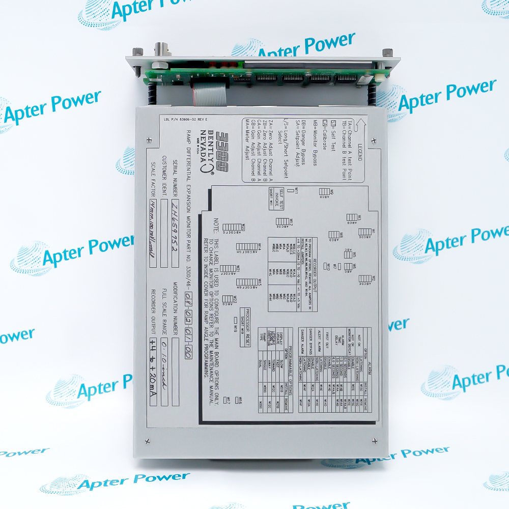
3300/55-01-04-12-12-00-00-05-01

Dual Velocity Monitor
In Stock
Ships by Saturday, November 7
Fast Shipping Available
Product image is representative; revision or series may vary. Contact us to request a specific version.

Product Describe:

Bently Nevada 3300/55-01-04-12-12-00-00-05-01 is a 3300/55 Dual Velocity Monitor configured for Channel A 0–20 mm/s pk; Channel B 0–20 mm/s pk with Velomitor, 100 mV/in/s; peak velocity; its selected hardware provides Epoxy-sealed alarm relays, a standard unbarriered input interface, no agency-approval option selected, 2X range multiplication.
Get a quick price for 3300/55-01-04-12-12-00-00-05-01
E-mail *
Mobile *
Company
Content *
Quantity *
Upload (gif, jpg, jpeg, png, bmp, doc, docx, xls, xlsx, ppt, pdf, csv)
For more information on how your data is processed and stored by Apterpower please read our privacy policy

What happens after you enquire

  • 1

    Requirement review

    We review the part number, quantity and delivery requirements and ask for any missing details.
  • 2

    Quotation and availability

    We confirm the proposed item, condition, availability, price and estimated lead time in the quotation.
  • 3

    Order confirmation and dispatch

    Once the quotation and purchasing details are agreed, your contact will coordinate the order and available dispatch information.

Technical specifications for 3300/55-01-04-12-12-00-00-05-01

  • Manufacturer:
    Bently Nevada
  • Product Category:
    Machinery Monitoring Systems
  • Spare Part Number:
    3300/55-01-04-12-12-00-00-05-01
  • Tariff Code:
    8537101190
  • Counliy of origin:
    USA
  • Measurement function:
    dual-channel velocity or integrated displacement
  • Selected channel ranges:
    Channel A 0–20 mm/s pk; Channel B 0–20 mm/s pk
  • Transducer and processing:
    Velomitor, 100 mV/in/s; peak velocity
  • Channel count:
    2 independent measurement channels
  • Alarm relay option:
    Epoxy-sealed
  • Safety-barrier option:
    None
  • Agency approval option:
    None
  • Range multiplier:
    2X
  • Channel comparison:
    Input, local indication and alarm response
  • Acceptance method:
    Independent response check for both channels

Information

Overview Manuals Common Applications Product Precautions
Bently Nevada 3300/55-01-04-12-12-00-00-05-01 applies two seismic or velocity-transducer channels with selectable measurement processing to absolute casing vibration monitoring, using the exact Channel A 0–20 mm/s pk; Channel B 0–20 mm/s pk scale and the selected interface options.
  • Uses the selected Channel A 0–20 mm/s pk; Channel B 0–20 mm/s pk measurement range.
  • Accepts Velomitor, 100 mV/in/s; peak velocity.
  • Uses epoxy-sealed alarm relay hardware.
  • Uses 2X range multiplication.

The complete channel must preserve the transducer source, displayed range, relay interface and barrier selection together. A monitor from the same family can produce a plausible indication while applying a different scale or output arrangement.

Important Notice: Match the complete 3300/55-01-04-12-12-00-00-05-01 order code, input source and rear connection assembly before installation; then verify each channel through a controlled response test.

Bently Nevada 3300/55-01-04-12-12-00-00-05-01 Manuals & Downloads
Bently Nevada 3300/55-01-04-12-12-00-00-05-01 Technical Reference (PDF)Bently Nevada 3300/55-01-04-12-12-00-00-05-01 Installation & Commissioning Guide (PDF)

The technical reference, installation guide and complete product information PDF are separate documents with different scopes. All three apply only to the exact model shown.


Absolute Casing Vibration Monitoring
Apply the selected Channel A 0–20 mm/s pk; Channel B 0–20 mm/s pk span to the intended machine measurement.
Two-channel condition monitoring
Keep channel identity from the field transducer through indication and alarms.
Controlled maintenance testing
Inject or apply a known change and compare each response stage.
Protection-system integration
Verify the selected relay and barrier interface with the receiving circuit.
Apply these checks to the exact Bently Nevada 3300/55-01-04-12-12-00-00-05-01 configuration before isolation, replacement or return to service.
1
Confirm the full 3300/55-01-04-12-12-00-00-05-01 marking before removing the installed monitor.
2
Record both channel readings and the selected Channel A 0–20 mm/s pk; Channel B 0–20 mm/s pk scale before isolation.
3
Preserve the Velomitor, 100 mV/in/s; peak velocity transducer and sensitivity selection.
4
Retain the epoxy-sealed relay arrangement and its contact logic.
5
Do not introduce a safety barrier without reviewing the complete input loop.
6
Do not infer an agency approval from another order-code variant.
7
Confirm the 2X multiplier during setpoint and recorder checks.
8
Test each channel, alarm state and downstream response before returning protection to service.

Technical notes

Use a controlled input condition to verify the Channel A 0–20 mm/s pk; Channel B 0–20 mm/s pk scale, Velomitor, 100 mV/in/s; peak velocity conversion, channel identity and selected output behavior. Restore the recorded alarm, delay, reset, multiplier and bypass states only after the complete path responds correctly.

FAQ View All FAQ

  • What does the selected Channel A 0–20 mm/s pk; Channel B 0–20 mm/s pk span control in 3300/55-01-04-12-12-00-00-05-01?
    The selected measurement span is Channel A 0–20 mm/s pk; Channel B 0–20 mm/s pk. Alarm and recorder scaling must be checked against that span rather than copied from a different range option.
  • What input-chain details must be retained for 3300/55-01-04-12-12-00-00-05-01?
    This configuration uses Velomitor, 100 mV/in/s; peak velocity. Preserve the transducer family, sensitivity and signal polarity as one measurement chain.
  • Which test separates 3300/55-01-04-12-12-00-00-05-01 measurement scaling from relay operation?
    The selected alarm output uses epoxy-sealed relay hardware. Contact logic, energization and downstream wiring still require a functional test.
  • How should field wiring be traced for the standard input interface of 3300/55-01-04-12-12-00-00-05-01?
    No safety-barrier option is selected. Do not move field conductors from a barrier-equipped circuit without an engineering review.
  • Should 3300/55-01-04-12-12-00-00-05-01 be treated as an agency-approved order-code variant?
    No agency-approval option is selected in this order code. Do not infer an approval from another unit in the same monitor family.
  • What must be checked before comparing 3300/55-01-04-12-12-00-00-05-01 with an unmultiplied monitor?
    The 2X multiplier expands the usable displayed range from the base scale. Confirm the multiplier state before comparing setpoints or recorder values.
  • What sequence verifies the indication and output path of 3300/55-01-04-12-12-00-00-05-01?
    Apply a controlled input change to one identified channel at a time, then compare the local indication, buffered or recorder signal, alarm state and return to normal.
  • What information prevents a wrong-variant replacement of 3300/55-01-04-12-12-00-00-05-01?
    Record the complete model, Channel A 0–20 mm/s pk; Channel B 0–20 mm/s pk scale, Velomitor, 100 mV/in/s; peak velocity input, relay and barrier choices, channel assignments, setpoints, delays and the observed acceptance results.
Related reading

Related cases and sourcing guidance

View all case studies
SPEAK TO OUR TEAM
Let’s find the right solution for you.
Send us the part number, quantity and delivery destination. Our team will help confirm availability and lead time.
  • Whatsapp: +86 18030235313

    Send us a message.
  • sales13@apterpower.com

    Complete our online form.
  • +86 18030235313

    Speak to our team in your native language.