-
Match the complete marking
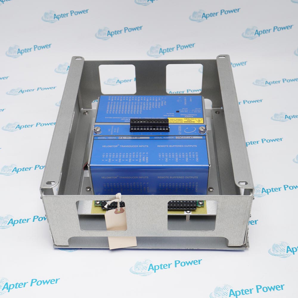
Include 1900/65A-01-01-03-00-01 and any revision or assembly number visible on the item. Keep the complete reference on the enquiry and quotation.
-
Check the offered item before ordering
Request available label and terminal photos. Have your maintenance team compare the offered 1900/65A-01-01-03-00-01 with the installed equipment and applicable Bently Nevada documentation.
Technical specifications for 1900/65A-01-01-03-00-01
-
Manufacturer:Bently Nevada
-
Product Category:Machinery Monitoring Systems
-
Spare Part Number:1900/65A-01-01-03-00-01
-
Weight:1.3 kg
-
Tariff Code:8537101190
-
Supply configuration:110-220 V AC, 50-60 Hz through an external supply
-
Display:Attached; no separate cable
-
Mounting / enclosure:fiberglass NEMA 4X/IP66 weatherproof housing with a window door
-
Monitor-side operating current:0.35 A typical; 1.0 A maximum
-
Monitor-side operating power:8.5 W typical; 14 W maximum
-
Transducer inputs:4; acceleration, velocity, radial vibration, thrust, position or speed
-
Temperature inputs:4; E/J/K/T thermocouples or 2-/3-wire RTDs
-
Relay outputs:6 SPDT; programmable logic
-
Maximum relay operands:50 per relay
-
Recorder outputs:4 x 4-20 mA; configurable channel/variable
-
Maximum recorder loop resistance:600 ohms
-
Recorder update interval:100 ms
-
Configuration retention:Non-volatile memory
-
Configuration interface:Built-in Ethernet
-
Modbus:Ethernet and RS232/RS485
Information
- Bently Nevada 1900/65A-01-01-03-00-01 combines local display access with digital supervisory reporting, so machine-condition values, status and event information can be integrated alongside relay and analog outputs.
Local access: Attached display; PC configuration through Ethernet
Communications: Modbus over Ethernet and configurable RS232/RS485 serial
Six SPDT relays can combine OK, Alert and Danger status through programmable expressions with up to 50 operands per relay. Latching and energized-state selections are independent. AND ignores bypassed channels while True AND includes them, which makes the exact voting expression significant during channel maintenance. Four independently assigned 4-20 mA outputs update every 100 ms and support up to 600 ohms loop resistance under the applicable loop-supply conditions.
The selected AC option uses an external 110-220 V AC, 50-60 Hz supply. A fiberglass NEMA 4X/IP66 housing with a window door accommodates local observation; cable entries and closure must preserve the enclosure installation. The Modbus Gateway makes static variables, status, event-list information and time/date information available to a supervisory system. The serial interface can be configured for RS232 or RS485; network and receiver settings must agree.

1900/65A-01-01-03-00-01 Official Technical Reference Excerpt
1900/65A General Purpose Equipment Monitor, 173401 Rev. AC: preserved manufacturer technical information applicable to this configuration. PDF · 9 pages.1900/65A-01-01-03-00-01 Installation & Verification Guide
Apter Power field guide covering display access, external AC power and enclosure preparation, relay tests and Modbus data verification. PDF · 5 pages.
Application scope: Suitable general-purpose machines may combine vibration, temperature and discrete protection. The examples describe integration roles, not preconfigured alarm settings or a universal machine-protection design.
Local condition display
Read configured channel values at the machine-monitoring position using the attached display.Combined thermal and vibration monitoring
Pair compatible bearing-temperature circuits with the selected vibration measurements.Programmable protection contacts
Use reviewed relay expressions to combine warning, danger and channel-health states.Digital supervisory reporting
Transfer measurements, status and events through the configured Modbus interface.
Check the external AC supply and maintain window-door housing closure and cable-entry sealing.
Record transducer type, sensitivity, wiring and temperature-sensor selection.
Use the site-approved maintenance state before altering relays or alarm settings.
Match each recorder variable and full scale to the receiving input.
Test normal, alarm, Not OK, bypass and reset behavior against the approved logic.
Record interface type, addressing, serial settings and receiver mapping before changing the gateway.
Alternative Names
Technical notes
Power boundary: 110-220 V AC, 50-60 Hz through an external supply. Monitor-side DC demand is not the AC mains input-current rating.
Display selection: The attached display is included without a separate display cable. Remote-display accessories are not implied.
Communication selection: The Modbus Gateway makes static variables, status, event-list information and time/date information available to a supervisory system. The serial interface can be configured for RS232 or RS485; network and receiver settings must agree.

FAQ View All FAQ
-
Which communication paths carry Modbus data from 1900/65A-01-01-03-00-01?The gateway supports Ethernet and a serial port configurable for RS232 or RS485. The selected electrical interface and communication settings must match the receiving system.
-
What can a supervisory system retrieve from 1900/65A-01-01-03-00-01?Modbus provides access to static variables, monitor status, event-list information and time/date information. Engineer the receiver mapping for the required data rather than treating all registers as equivalent measurements.
-
How should event time be coordinated for 1900/65A-01-01-03-00-01?The monitor time counter uses a reference supplied through the Modbus master. Include time/date synchronization in commissioning so the event sequence can be compared with supervisory-system records.
-
Does Modbus replace the recorder outputs on 1900/65A-01-01-03-00-01?No. Four independently assigned 4-20 mA recorders remain available alongside the digital interface. Compare the same variable and scaling when checking digital and analog readings.
-
Which part of 1900/65A-01-01-03-00-01 accepts the selected mains supply?An external power supply implements the 110-220 V AC, 50-60 Hz option. The monitor itself uses the DC side; its DC consumption values are not mains input-current specifications.
-
How is local viewing preserved in the enclosed 1900/65A-01-01-03-00-01 configuration?The build combines an attached display with a fiberglass NEMA 4X/IP66 housing and window door. Maintain the housing seals and cable entries when arranging local access.
-
Can 1900/65A-01-01-03-00-01 communicate a valid value while the alarm logic is configured incorrectly?Yes. Data transport alone does not prove protective logic. Independently test Alert, Danger, Not OK, bypass and physical relay response against the approved expressions.
-
Which settings deserve separate checks when replacing 1900/65A-01-01-03-00-01?Retain sensor processing, relay expressions, recorder assignments and the Modbus interface configuration. Verify host mapping and event-time synchronization as well as the local display and measured values.
Supporting new and legacy automation
-
Please try to be as accurate as possible with your search.
-
We can quote you on 1000s of specialist parts, even if they are not listed on our website.
-
We can't find any results for “”.
Related cases and sourcing guidance
View all case studiesYou May Also Like
Product Browsing History
-
Whatsapp: +86 18030235313
Send us a message. -
sales13@apterpower.com
Complete our online form. -
+86 18030235313
Speak to our team in your native language.