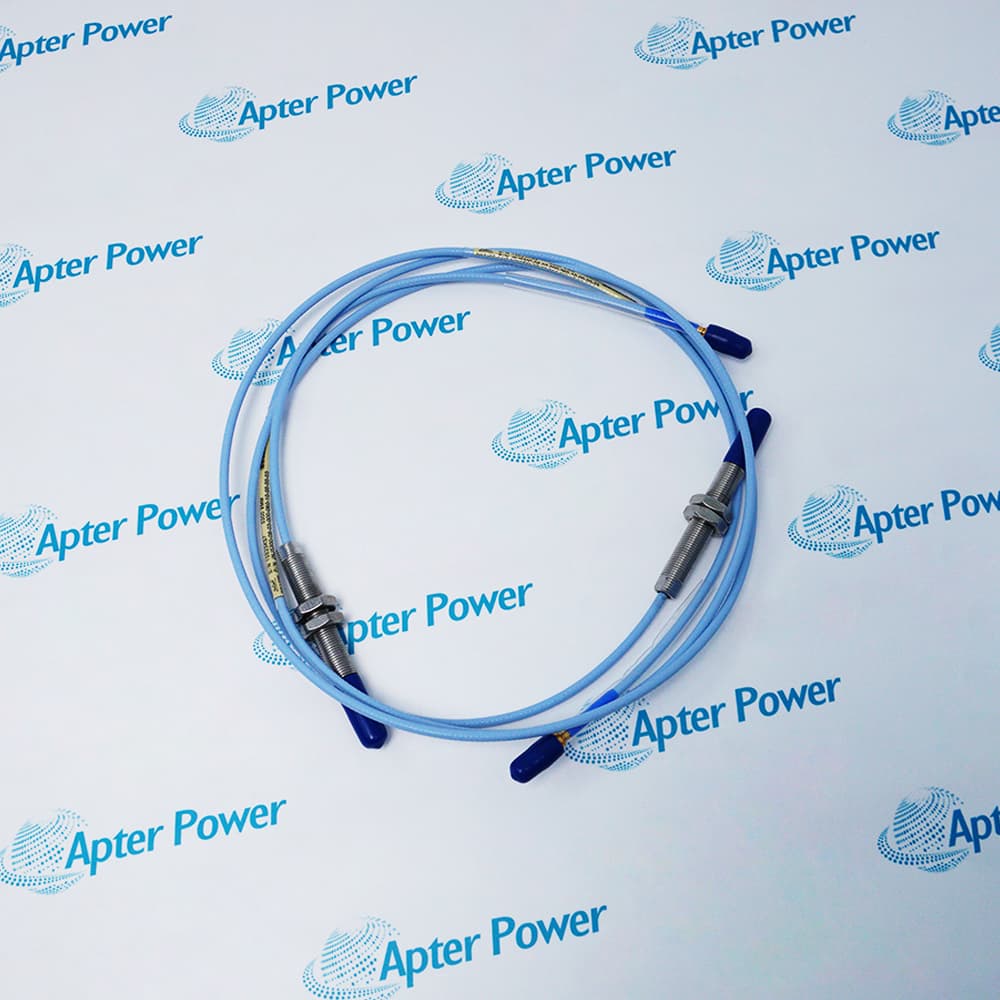
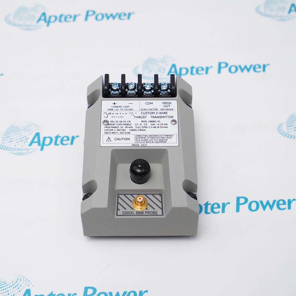
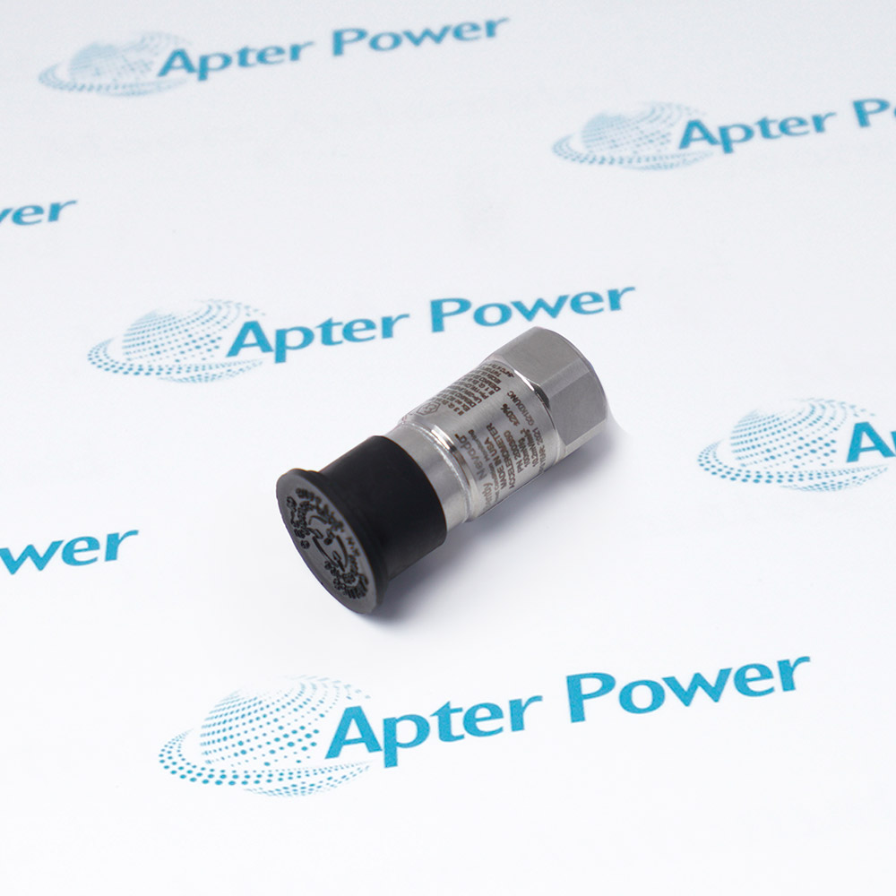
Bently Nevada 146054-34-20-02-05 is a configured proximity-probe assembly for a compatible 3300 measurement system.
- Proximity measurement chain
- Configured probe assembly
- Machine-condition monitoring
- Matched-system installation
146054-34-20-02-05 is installed as part of a matched Bently Nevada proximity measurement chain. Confirm the specified extension cable, driver, probe mounting, target gap, connector engagement and monitoring-channel configuration before completing vibration or position verification.
Important Notice: Confirm whether the required rack hardware, matched transducer chain, extension leads and configured protection accessories for 146054-34-20-02-05 are included in the quotation or stock description.
Apter Power 146054-34-20-02-05 Manuals and Guides
Important Notice: These are two separate Apter Power documents independently prepared from manufacturer-published information. Confirm the physical nameplate, current manufacturer documents and installed-system requirements before configuration or installation. They do not replace manufacturer manuals.
146054-34-20-02-05 installed-base maintenanceSupports like-for-like service of the documented configured 3300 ceramic-capped proximity probe.
146054-34-20-02-05 compatibility reviewChecks host hardware, revision, companion components, wiring and configuration before replacement.
146054-34-20-02-05 installation planningDefines isolation, ESD, mounting, connection and parameter checks before field work.
146054-34-20-02-05 commissioningSupports controlled diagnostic, channel, communication or process-response checks after installation.
Read the applicable Baker Hughes / Bently Nevada instructions before work. Verify 146054-34-20-02-05 and the installed-system configuration.
1Verify model 146054-34-20-02-05 and the complete order code on the physical label before use.
2Confirm all four option blocks, protect the unsealed rear from destructive liquids or gases, preserve total system length and electrically gap the probe without touching the target.
3Match every 146054-34-20-02-05 connector, terminal, cable and companion assembly before moving field wiring.
4Back up the applicable controller, monitor, HMI or I/O configuration before replacing 146054-34-20-02-05.
5Isolate energy and follow the approved site safety procedure before handling 146054-34-20-02-05.
6Follow ESD controls and protect 146054-34-20-02-05 connectors and printed-circuit assemblies during handling.
7Do not transfer ratings or suffix meanings from a similar model to 146054-34-20-02-05.
8After installing 146054-34-20-02-05, complete the relevant power, channel, link, diagnostic, alarm and fail-state checks.


 Videos
 News
News Applications