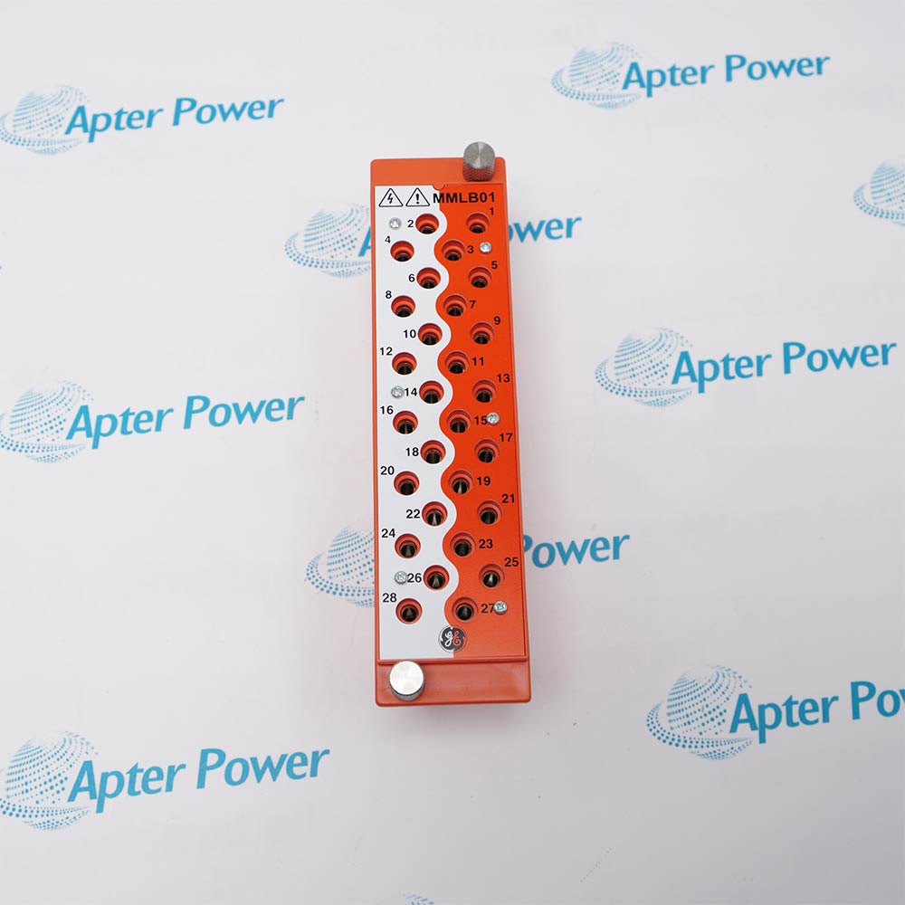
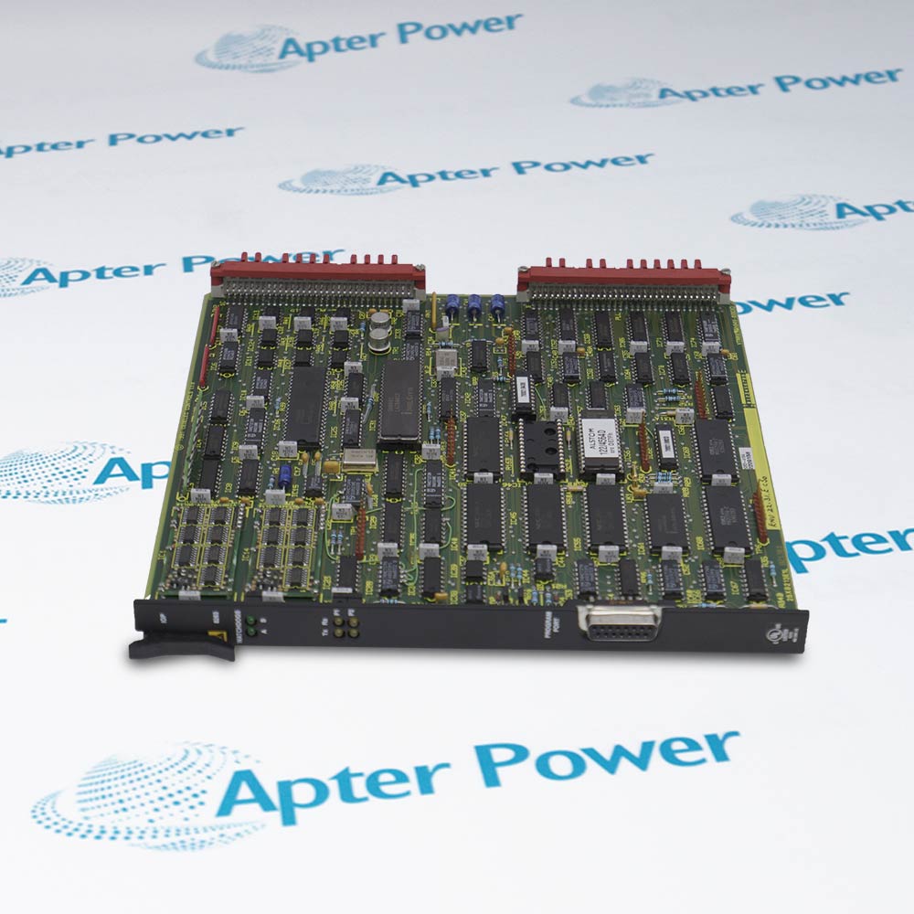
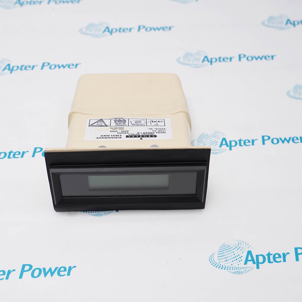
Transfers controller logic commands from a CE2000 rack to field devices through static powered-negative output circuits.
- Signal or energy path: Backplane logic selects the output state, and the module switches the external process supply to the assigned actuator or interposing circuit without mechanical output contacts.
- Companion components: Use the approved CE2000 controller rack, process-supply distribution, terminal wiring and field interface devices for the installed ALSPA system.
- Engineering check: Verify output mapping, supply return, load compatibility, channel isolation and fail-state behavior against the project drawings.
- System boundary: Output behavior depends on the CE2000 channel mapping, external process supply and documented field-load interface.
Industrial application: Legacy ALSPA power-plant and industrial process-control installations.
Important Notice: Verify the complete LD106 nameplate, installed-system documentation, companion hardware and current Alstom instructions before installation or replacement.
Apter Power LD106 Manuals and Guides
Important Notice: The first link is the product-parameters PDF prepared only from the cited manufacturer information; the second link is the Apter Power product manual. Confirm the physical nameplate, current manufacturer documents, and host-system requirements before installation or replacement.
Existing ALSPA P320 discrete output maintenance
Restores or maintains a site-matched bank of 16 static 48 VDC logic outputs in a CE2000 controller.
Power-plant actuator command circuits
Switches engineered on/off commands to compatible 48 VDC actuator interface circuits in thermal, combined-cycle or hydro plant automation.
Industrial and substation P320 control cells
Provides site-specific discrete outputs in ALSPA P320 automation cells used for substations or high-availability industrial processes described by the OEM system manual.
ALSPA-to-Mark VIe smart retrofit
Retains compatible LD106 I/O and process wiring while the control layer migrates through a project-engineered PCEG/Mark VIe solution.
Read and follow the current Alstom documentation and host-equipment instructions before work. Verify the complete physical nameplate and system configuration.
1
Require an ALSTOM/ALSPA nameplate and CE2000 slot/wiring context; the bare code LD106 is not unique enough for identification.
2
Resolve the official-document conflict before energization: the ALSTOM hardware table says 16 logic outputs, while GEI-100746 says 16 static digital inputs.
3
Verify the exact 48 VDC powered negative-output wiring and load polarity from the unit drawing; do not translate 'negative output' into a sourcing/sinking claim without the technical data sheet.
4
Do not assume per-channel current, total load, fuse/protection, isolation, leakage, response time or safe-state values; none were verified in the reviewed official exact-module sources.
5
Do not substitute LC105, LC106 or LE-series modules by point count alone; their signal direction, switching method, voltage and isolation differ.


 Videos
 News
News Applications