Speak to a sourcing specialist
sales13@apterpower.com

1769-IQ32

Digital Input Module
In Stock
Ships by Monday, November 9
Fast Shipping Available
AB 1769-IQ32 (1)
AB 1769-IQ32 (2)
AB 1769-IQ32 (3)
AB 1769-IQ32 (1)
AB 1769-IQ32 (2)
AB 1769-IQ32 (3)
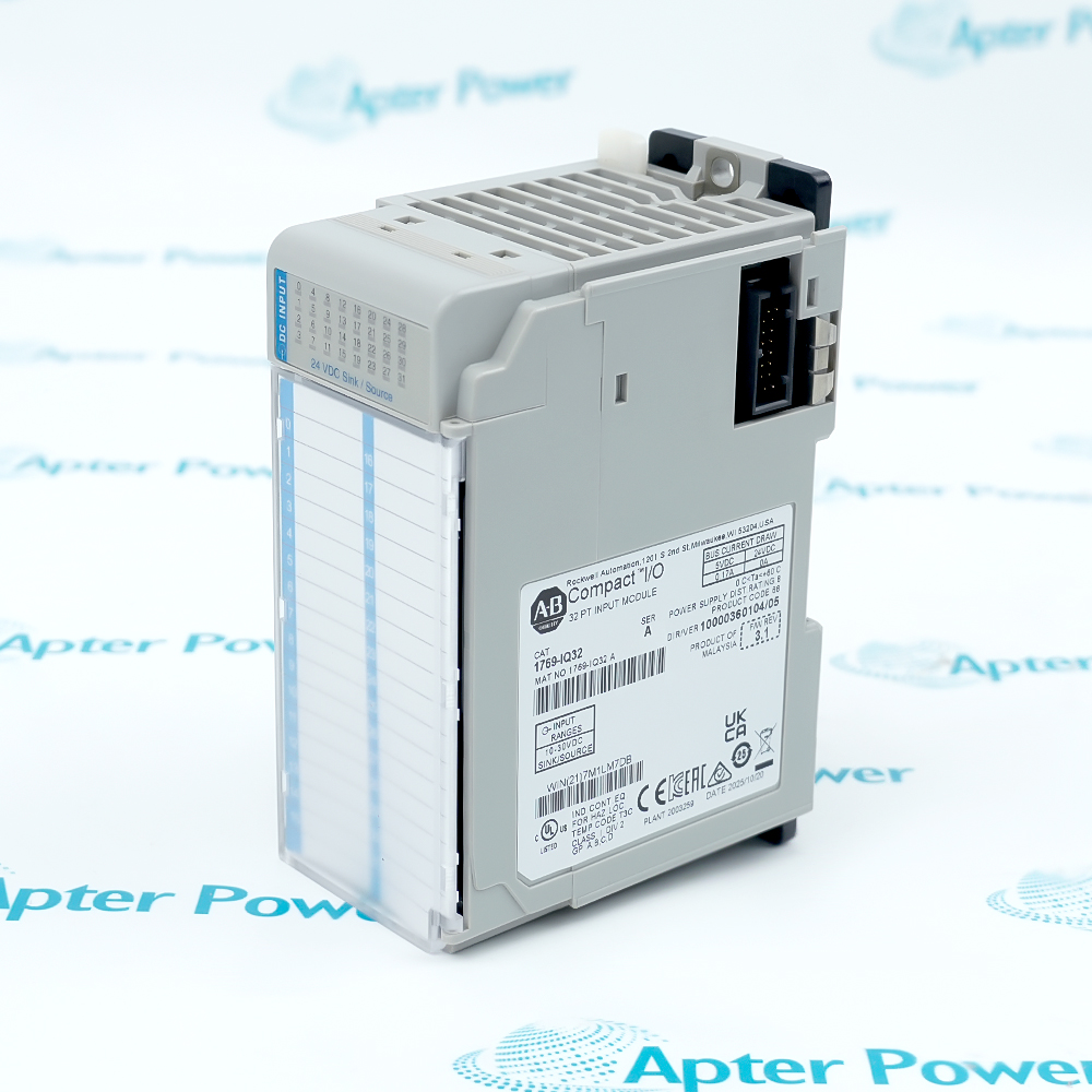
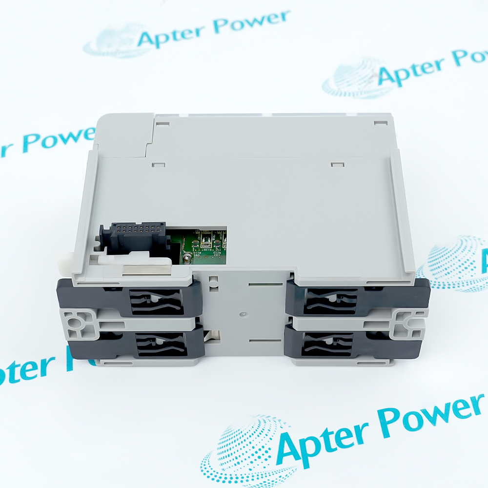
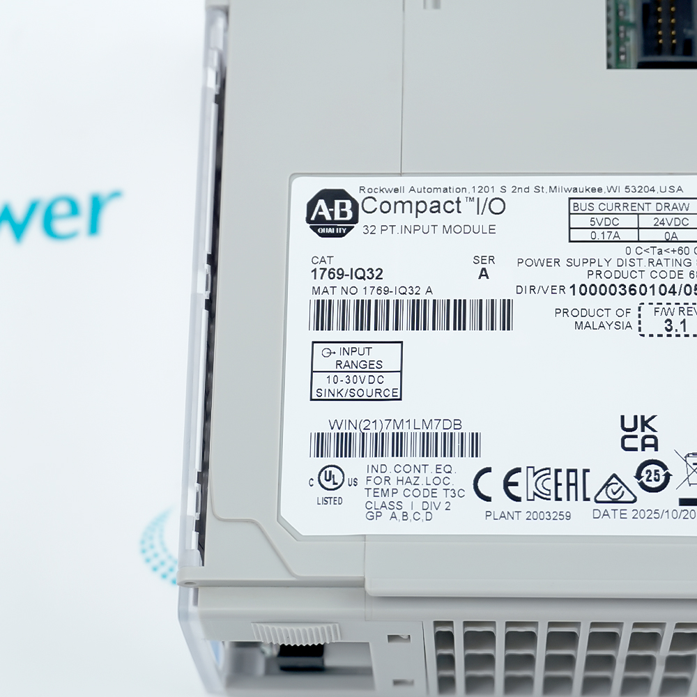
Product image is representative; revision or series may vary. Contact us to request a specific version.

Product Describe:

Allen-Bradley 1769-IQ32 is a 32-point, 24 V DC sinking/sourcing input module that transfers discrete field-device states to a Compact I/O controller system.
Get a quick price for 1769-IQ32
E-mail *
Mobile *
Company
Content *
Quantity *
Upload (gif, jpg, jpeg, png, bmp, doc, docx, xls, xlsx, ppt, pdf, csv)
For more information on how your data is processed and stored by Apterpower please read our privacy policy

What happens after you enquire

  • 1

    Requirement review

    We review the part number, quantity and delivery requirements and ask for any missing details.
  • 2

    Quotation and availability

    We confirm the proposed item, condition, availability, price and estimated lead time in the quotation.
  • 3

    Order confirmation and dispatch

    Once the quotation and purchasing details are agreed, your contact will coordinate the order and available dispatch information.

Technical specifications for 1769-IQ32

  • Manufacturer:
    Allen-Bradley
  • Product Category:
    PLC Systems
  • Spare Part Number:
    1769-IQ32
  • Estimated shipping dimensions:
    4×8.8×13.2cm
  • Weight:
    0.12 kg
  • Tariff Code:
    8537101190
  • Counliy of origin:
    USA
  • Digital inputs:
    32
  • Input grouping:
    4 isolated groups; 8 points per group
  • Signal category:
    24 V DC sink/source
  • Operating input range:
    10-30 V DC at 30 °C; 10-26.4 V DC at 60 °C
  • Maximum input delay:
    8 ms ON; 8 ms OFF
  • Backplane current at 5.1 V:
    170 mA
  • Maximum heat dissipation:
    4.6 W
  • Maximum OFF-state voltage:
    5 V DC
  • Maximum OFF-state current:
    1.5 mA
  • Minimum ON-state voltage:
    10 V DC
  • Minimum ON-state current:
    2 mA
  • Maximum input inrush:
    250 mA
  • Nominal input impedance:
    5.2 kΩ at 24 V DC; 6.1 kΩ at 30 V DC
  • Isolation test:
    1200 V AC or 1697 V DC for 1 s
  • Working isolation voltage:
    75 V DC; IEC Class II reinforced insulation
  • Power-supply distance rating:
    8 modules
  • Input data image:
    2 words × 16 bits; read-only
  • IEC input compatibility:
    Type 1+
  • Terminal screw torque:
    0.68 N·m
  • Terminal-block retaining torque:
    0.46 N·m
  • Solid conductor range:
    22-14 AWG copper, 90 °C
  • Stranded conductor range:
    22-16 AWG copper, 90 °C
  • Operating temperature:
    0-60 °C
  • Storage temperature:
    -40 to 85 °C
  • Operating humidity:
    5-95% RH, noncondensing
  • Enclosure rating:
    Open style
  • Electronic identification:
    Vendor 1; product type 7; product code 68

Information

Overview Manuals Common Applications Product Precautions
Allen-Bradley 1769-IQ32 lets a machine panel arrange its input circuits in four electrically isolated groups, so each group can follow the polarity of its connected field devices.
  • Provides individual front-panel indication for the input points.
  • Uses removable, finger-safe terminal blocks for field connections.
  • Supports mechanically interlocked Compact I/O bus connections.
  • Offers DIN-rail and panel mounting for industrial enclosures.

The controller reads the input image as two 16-bit words. Channel numbering continues across both words, so an application that monitors only the first word will omit half of the available field states.

Important Notice: Check both halves of the input image against the terminal labels before releasing the machine to automatic operation.

Allen-Bradley 1769-IQ32 Manuals & Downloads
Allen-Bradley 1769-IQ32 Manufacturer Installation Instructions — Selected Pages (PDF)Allen-Bradley 1769-IQ32 Installation & Commissioning Guide (PDF)

The installation instructions include wiring diagrams and electrical ratings. The field guide covers work preparation, replacement, commissioning and fault isolation.

Machine sequence feedback
Collect limit-switch and proximity-sensor states for sequence logic that uses conventional discrete DC inputs.
Grouped panel wiring
Allocate different field circuits to separate input groups while keeping each group’s common and signal conductors together.
Dense status acquisition
Bring numerous equipment-ready, contact and position indications into one Compact I/O assembly.
Maintainable I/O stations
Use removable termination and individual indicators to support circuit tracing during planned service.
Installation and service checks for Allen-Bradley 1769-IQ32.
1
Isolate the controller-side supply and field circuits before inserting or removing the module.
2
Discharge static electricity before handling the bus connectors or circuit assembly.
3
Keep drilling debris and stripped conductor fragments out of the module openings.
4
Lock the module bus lever fully left after aligning the adjacent connectors.
5
Do not connect the DC input terminals to an AC power source.
6
Keep the finger-safe cover in place while terminating field wires.
7
Use a grounded metal mounting surface and keep the ventilation paths unobstructed.
8
Restore terminal identification labels so the complete channel-to-field-device mapping remains readable.

Technical notes

Use the correct DC common for each eight-point circuit group. A common-wire fault can affect an entire group even when the controller still recognizes the module.

FAQ View All FAQ

  • Can separate 1769-IQ32 input groups use different sinking and sourcing arrangements?
    Yes. The four isolated groups can operate in either configuration. Keep the polarity and DC common consistent within each group of eight; do not treat every point as an independently isolated circuit.
  • Why does reading only word 0 leave some 1769-IQ32 signals out of the controller application?
    The input image contains words 0 and 1, with sixteen readable bit positions in each. The application must include both words to use all thirty-two input states.
  • Which circuit should be checked when only inputs 16-23 on 1769-IQ32 stop responding?
    These eight inputs belong to the group using DC COM 3. Check that group’s field supply, common conductor and polarity before investigating the other three groups.
  • How should two conductors be selected for one 1769-IQ32 wiring terminal?
    Each terminal accepts up to two conductors within the specified ranges: 22-14 AWG solid copper or 22-16 AWG stranded copper, with a 90 °C wire rating. Secure both conductors under the pressure plate and verify neither is loose.
  • What terminates the Compact I/O bus when 1769-IQ32 is the last module?
    Fit and lock the appropriate 1769-ECR right end cap or 1769-ECL left end cap. A mechanically complete row still requires its bus terminator.
  • Does the 1200 V AC isolation test make 1769-IQ32 suitable for a 1200 V operating circuit?
    No. That value is a one-second dielectric test, not a continuous operating rating. The working isolation voltage is 75 V DC, and the field inputs remain low-voltage DC circuits.
  • Can the wired terminal block be detached while replacing a 1769-IQ32?
    Yes, after power is removed. Identify the terminal block’s left or right position, loosen its retaining screws, and retain the existing field-wire assignments while the module is exchanged.
  • Why must the neighboring bus lever be released before a mounted 1769-IQ32 is withdrawn?
    The right-hand neighboring module is mechanically and electrically connected to the unit being removed. Unlock that connection as well as the target module’s lever before sliding the module forward, then relock both interfaces after replacement.
Manufacturers

Product Browsing History

Revisit the products you recently viewed on Apter Power.
SPEAK TO OUR TEAM
Let’s find the right solution for you.
Send us the part number, quantity and delivery destination. Our team will help confirm availability and lead time.
  • Whatsapp: +86 18030235313

    Send us a message.
  • sales13@apterpower.com

    Complete our online form.
  • +86 18030235313

    Speak to our team in your native language.