










Get Parts Quote
Name
Company *
Phone *
Email *
Address
City
State / Province / Region
Zipcode
Country
Quantity *
Part Number *
Manufacturer
Preferred Condition
Additional Information
Cancel
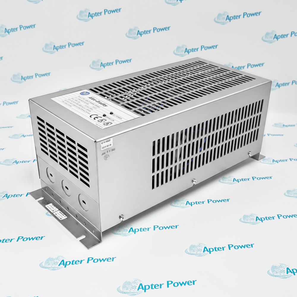
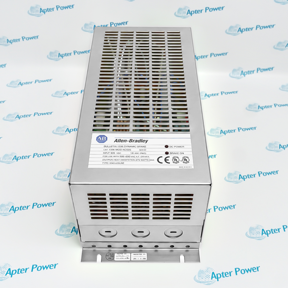
Allen-Bradley 1336-MOD-KC005
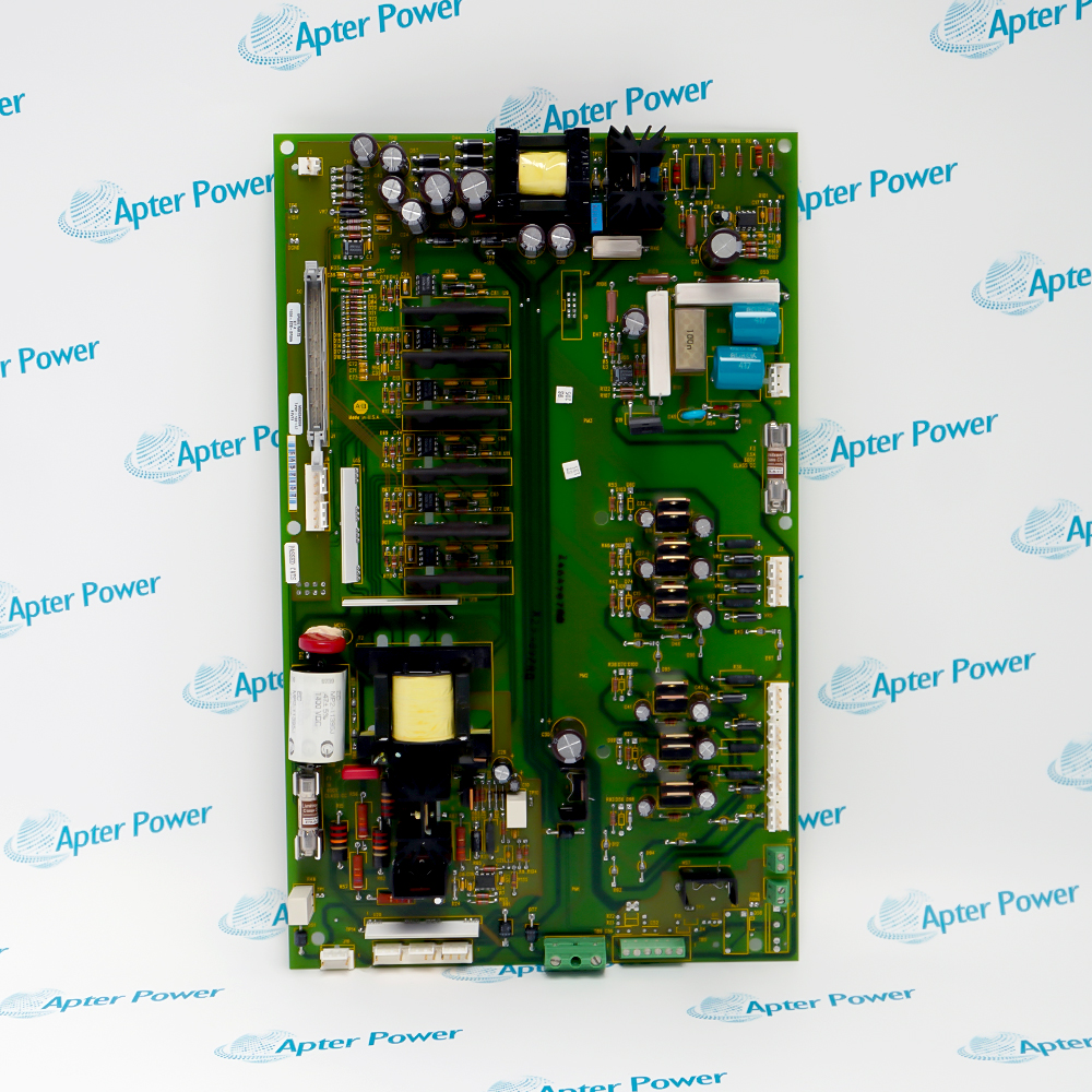
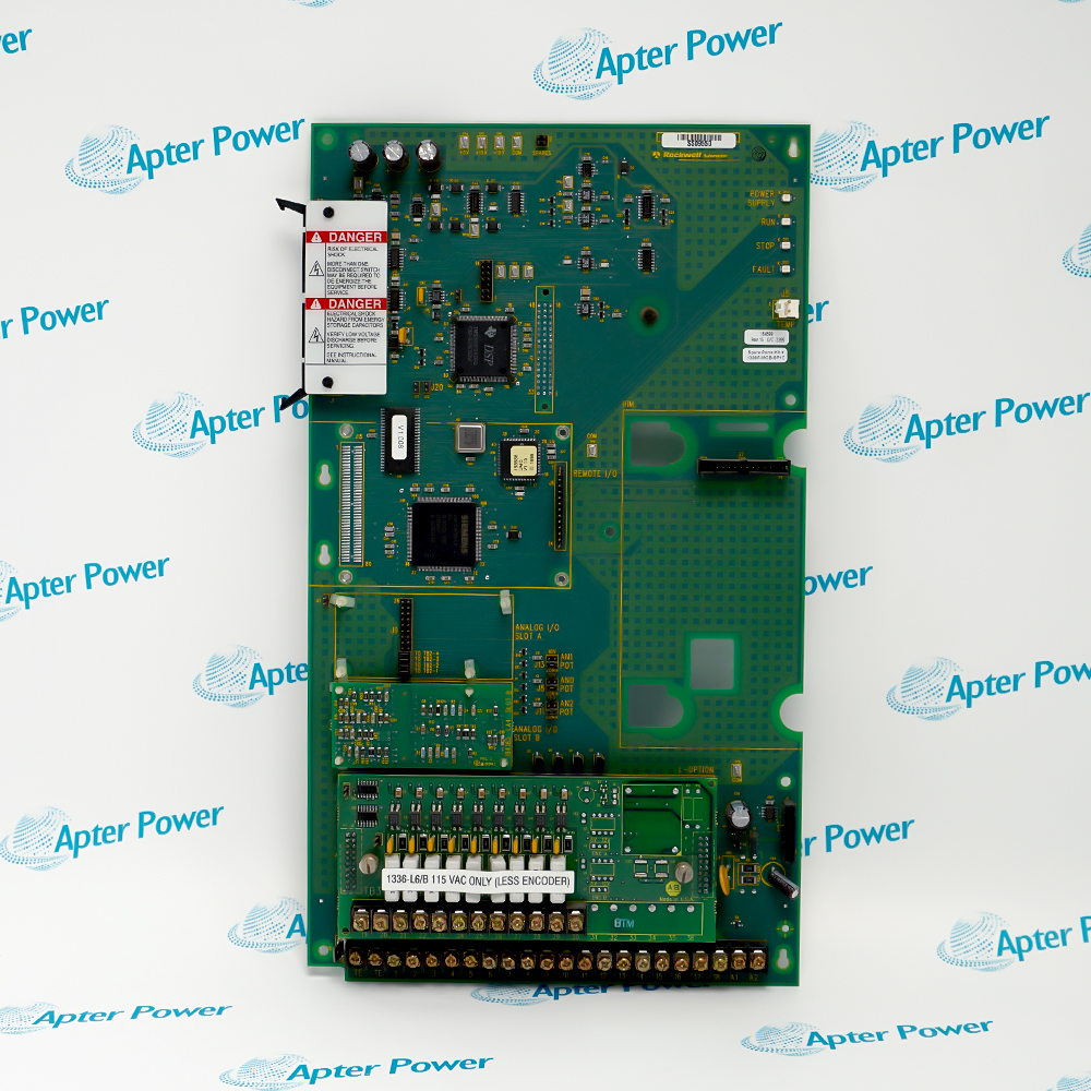
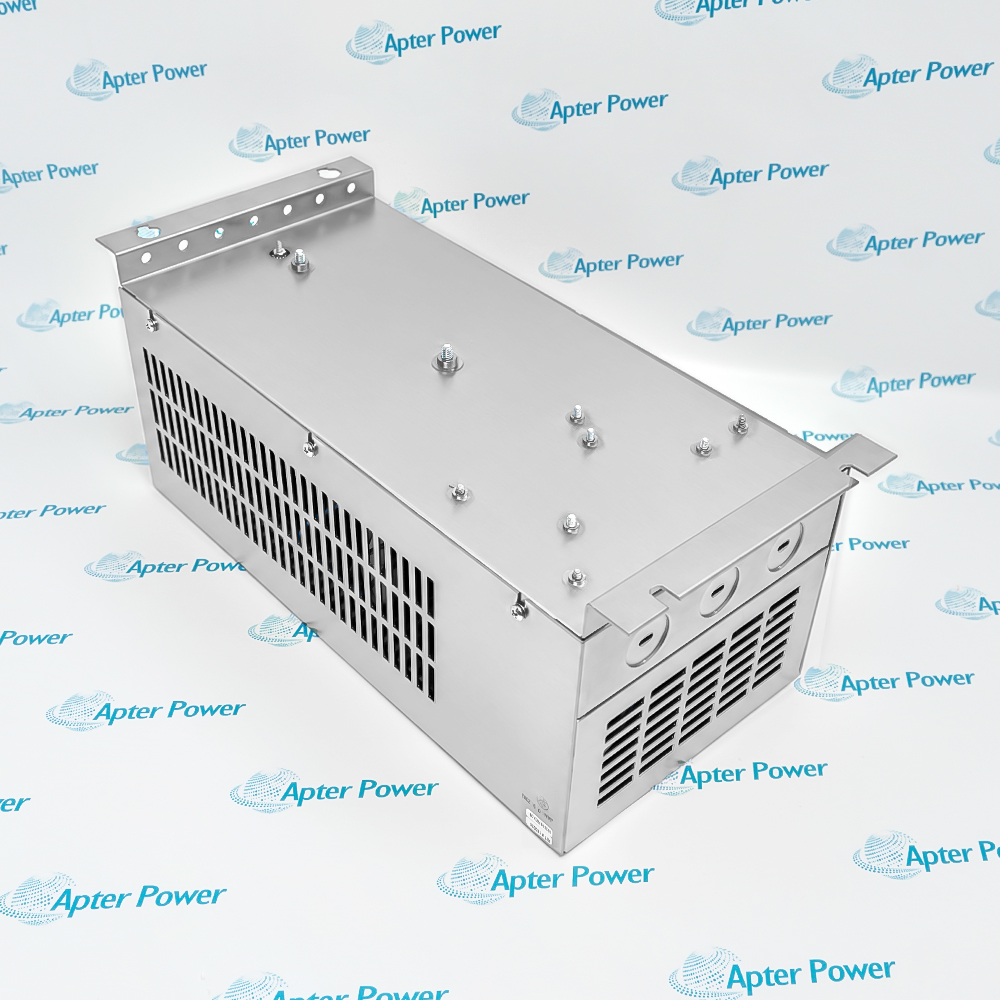
Product image is representative; revision or series may vary. Contact us to request a specific version.

1336-MOD-KC005

Dynamic Brake Module
In Stock
Ships by Wednesday, October 14
Fast Shipping Available

Product Describe:

Allen-Bradley 1336-MOD-KC005 combines a DC-bus chopper circuit and brake resistor in an IP20 enclosure. The KC005 module supports intermittent regenerative braking and can participate in a configured master-and-follower brake group.

Ask our team:

Get a quick price for: 1336-MOD-KC005
Quantity*
Upload (gif, jpg, jpeg, png, bmp, doc, docx, xls, xlsx, ppt, pdf, csv)
For more information on how your data is processed and stored by Apterpower please read our privacy policy.

Technical specifications for 1336-MOD-KC005

Technical specifications for 1336-MOD-KC005

  • Manufacturer:
    Allen-Bradley
  • Product Category:
    General Automation
  • Spare Part Number:
    1336-MOD-KC005
  • Estimated shipping dimensions:
    19.5x17.5x44.5cm
  • Weight:
    6.98 kg
  • Tariff Code:
    8537101190
  • Counliy of origin:
    Xiamen, Fujian, China
  • Product type (Series D):
    Heavy-duty dynamic brake module
  • Host-drive voltage class (Series D):
    500/575 V AC; brake power is from the DC bus
  • Brake power input (Series D):
    Drive DC bus
  • Brake resistor (Series D):
    108 ohms
  • Average resistor dissipation (Series D):
    1500 W
  • Turn-on voltage at 575 V AC (Series D):
    937.5 V DC
  • Braking torque (Series D):
    100% for 20 seconds, typical
  • Duty cycle (Series D):
    20%, typical
  • Enclosure (Series D):
    IP20 / NEMA Type 1
  • Operating temperature (Series D):
    -10 to 50 C
  • Humidity (Series D):
    5 to 95%, non-condensing
  • Altitude without derating (Series D):
    1000 m maximum
  • Internal fuse (Series D):
    F1, FWP-5 or equivalent
  • Fuse rating (Series D):
    5 A, 700 V
  • Master jumper W1 (Series D):
    Positions 2 and 3
  • Follower jumper W1 (Series D):
    Positions 1 and 2
  • Voltage-select jumper W2 (Series D):
    Not provided on KC brakes
  • Optional fault monitoring supply (Series D):
    115 V AC, 50 mA
  • Fault contact state (Series D):
    Normally open; closed with monitoring power, opens on fault or power loss
  • Status indicators (Series D):
    DC Power / Brake On
  • Mounting orientation (Series D):
    Vertical, outside other cabinets
  • Single KC005 DC wiring minimum (Series D):
    4 mm2 / 12 AWG for C003-C005 drive ratings

Information

Information

Overview Manuals Common Applications Product Precautions
Allen-Bradley 1336-MOD-KC005 is a heavy-duty dynamic brake module for the 500/575 V AC class of 1336 drives.
  • Coordinates a master-and-follower braking group
  • Indicates applied bus power and chopper activity
  • Isolates abnormal chopper conditions with fuse protection
  • Converts regenerated electrical energy into resistor heat

Brake selection uses motor inertia, operating speed and the timed regenerative cycle. Peak demand and average thermal load are evaluated separately before choosing a single module or a parallel arrangement.

Important Notice: The auxiliary 115 V AC supply is for optional fault-contact monitoring, not the KC005 brake power input. Verify zero voltage between the drive +DC and -DC terminals before terminal access.

Allen-Bradley 1336-MOD-KC005 Manuals & Downloads
Allen-Bradley 1336-MOD-KC005 Technical Reference (PDF)Allen-Bradley 1336-MOD-KC005 Dynamic Braking Installation Data (PDF)

The technical reference separates braking capability, master/follower configuration and fault decisions. The original installation manual supplies Series D wiring, fuse selection and commissioning details.


Intermittent regenerative deceleration
Dissipates periodic braking energy from a correctly matched 1336 drive DC bus.
Parallel braking coordination
Uses one master and configured follower modules when calculated brake demand requires a parallel group.
Remote brake fault integration
Signals fuse or thermostat faults to the connected control circuit through the powered monitoring contact.
Thermal-cycle selection
Separates peak regenerative demand from average resistor dissipation when assessing a repeated speed profile.
Read the Allen-Bradley dynamic braking installation instructions before work. Match 1336-MOD-KC005, the installed brake series and the drive DC-bus class before isolation or commissioning.
1
Match the complete KC005 identity and the drive voltage class before connection.
2
Remove all power, wait at least one minute and measure zero voltage between +DC and -DC before service.
3
Mount vertically outside other cabinets with unrestricted circulating air and the prescribed clearance.
4
Ground the brake frame and use twisted-pair DC wiring in conduit separate from control wiring.
5
Set W1 for exactly one master and the required followers; do not look for a KC input-voltage jumper.
6
Retain MASTER OUT jumpers according to the single-brake or final-enclosure wiring scheme.
7
Provide the separate monitoring supply only where the optional brake fault contact is used.
8
Check fuse type, indicators and calculated peak/average brake loading before restoring the controlled process.

Technical notes

Technical notes

KC005 has no W2 input-voltage jumper. W1 selects master or follower operation; only one master is permitted per brake group. Keep the factory MASTER OUT jumper for a single brake and retain it only in the last enclosure of a multi-brake chain. Values are taken from Series D installation data; the requested code does not independently establish the physical unit's series.

FAQS

  • What does a flickering Brake On lamp mean on 1336-MOD-KC005?
    It indicates that the chopper circuit is switching the brake resistor. The separate DC Power lamp indicates applied DC-bus power; the two lamps do not report the same condition.
  • Does KC005 use the W2 voltage selector shown for KB brake units?
    No. KC brakes do not have an input-voltage jumper. Do not copy the KB 380/460 V jumper settings to this module.
  • How is leadership assigned in a parallel KC005 brake group?
    Use exactly one master. Leave that module's W1 jumper at positions 2 and 3; move W1 to positions 1 and 2 in each follower enclosure.
  • Should the MASTER OUT jumper be removed from a single KC005?
    Keep the factory jumper in a single-brake installation. In a multi-brake chain, remove it from all enclosures except the last one.
  • Is 115 V AC needed to power the KC005 braking circuit?
    The braking circuit is supplied by the drive DC bus. A separate 115 V AC, 50 mA supply is needed only when the optional brake fault contact is monitored; the fan-power requirement applies to KC050, not KC005.
  • Which conditions open the monitored brake fault contact?
    A blown brake fuse or tripped brake thermostat opens the contact. Loss of the monitoring supply also opens it, so an open indication should be checked against both brake condition and auxiliary power.
  • Why must F1 replacement retain the 5 A, 700 V rating?
    KC005 specifies an FWP-5 fuse or equivalent. The fuse works with the crowbar protection to isolate an abnormal chopper circuit from the DC bus; a different rating changes that protective coordination.
  • Does the 1500 W resistor figure define the entire braking selection?
    No. It is average resistor dissipation. Evaluate peak regenerative demand against the 108-ohm resistance, then check average and transient thermal loading for the actual deceleration cycle.
Trusted by 5,000+ plants worldwide | Backed by our vast inventory of top-tier control parts, modules and cards, fast shipments are dispatched to cover your urgent needs. ABOUT US >>
Disclaimer: We are not an authorized distributor or distributor of the product manufacturer of this website, The product may have older date codes or be an older series than that available direct from the factory or authorized dealers. Because our company is not an authorized distributor of this product, the Original Manufacturer`s warranty does not apply.While many DCS PLC products will have firmware already installed, Our company makes no representation as to whether a DSC PLC product will or will not have firmware and, if it does have firmware, whether the firmware is the revision level that you need for your application. Our company also makes no representations as to your ability or right to download or otherwise obtain firmware for the product from our company, its distributors, or any other source. Our company also makes no representations as to your right to install any such firmware on the product. Our company will not obtain or supply firmware on your behalf. It is your obligation to comply with the terms of any End-User License Agreement or similar document related to obtaining or installing firmware.

We’re Here When You Need Us

From product insights to customer service needs, our experienced service team will focus on getting you what you need quickly

Enquire

Complete our online form.

Call Us

Speak to one of our team.

Live Chat

Send us a message.

