-
Match the complete marking
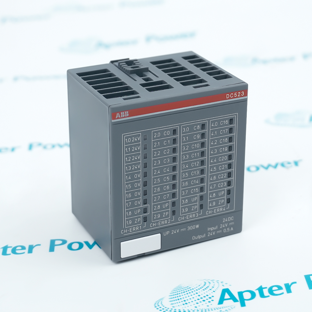
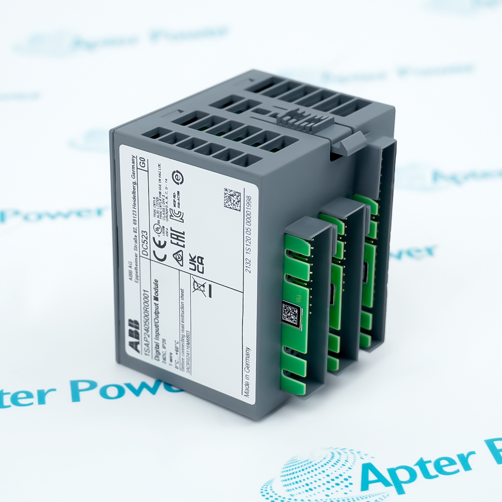
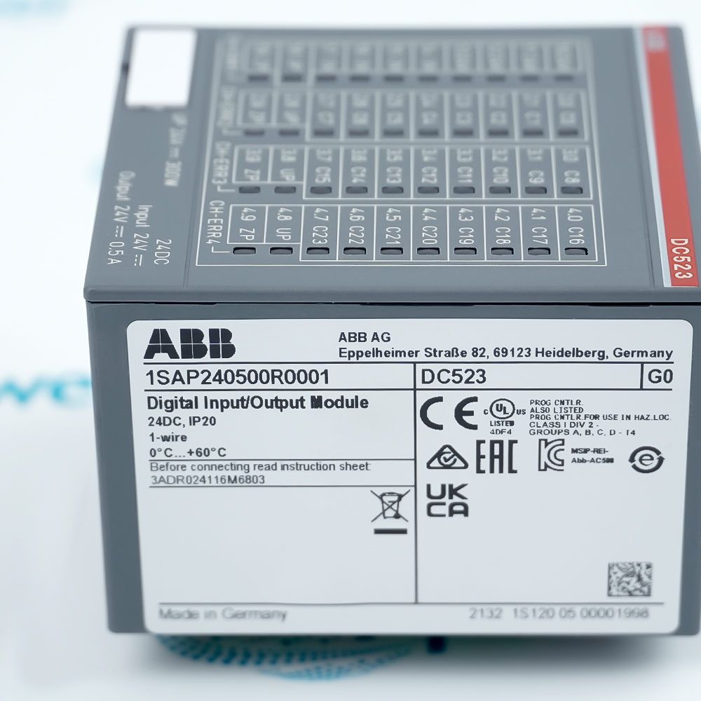
Compare DC523-1SAP240500R0001 with the complete installed nameplate and product ID.
-
Check the offered item before ordering
Confirm the DC523 electronic module, terminal-unit requirement and the installed field wiring. A terminal unit or communication interface is included only when itemized in the quotation.
Technical specifications for DC523-1SAP240500R0001
-
Manufacturer:ABB
-
Product Category:PLC Systems
-
Spare Part Number:DC523-1SAP240500R0001
-
Weight:0.1 kg
-
Tariff Code:8537101190
-
Type designation:DC523
-
Product ID:1SAP240500R0001
-
System family:S500 I/O for AC500
-
Configurable digital channels:24; each selectable as input or output
-
Process voltage UP:24 V DC nominal
-
Output technology:Transistor
-
Rated output per channel:0.5 A at UP = 24 V DC
-
Maximum aggregate output current:8 A
-
Input characteristic:EN 61131-2 Type 1
-
Input signal 0:-3 to +5 V DC
-
Input signal 1:+15 to +30 V DC
-
Input delay:8 ms typical; configurable 0.1-32 ms
-
Input current at 24 V DC:5 mA typical
-
Signal-1 output voltage:UP minus 0.8 V
-
Output readback:Supported
-
Output short-circuit protection:With automatic reclosure
-
Module isolation:Galvanic isolation per module
-
Required terminal unit:TU515 or TU516; selected separately
-
Module electronics supply:Internal I/O extension bus
-
Fieldbus access:Via AC500 CPU or communication interface module
-
Internal addressing:Automatic
Information
- In an AC500 station, ABB DC523-1SAP240500R0001 links binary field devices to the S500 I/O bus. Configure the channel directions in the controller project and match the terminal unit to the field wiring.
Channel allocation: 24 digital inputs/outputs
Output rating: 24 V DC, 0.5 A per channel
The transistor outputs switch 24 V DC loads at a nominal 0.5 A per channel, with an 8 A maximum aggregate output current. At signal 1, the output voltage is the process supply UP minus 0.8 V. Output readback and current limiting with automatic reclosure support field-circuit diagnosis; these functions must be considered together with the connected load and external circuit protection.
The module electronics are supplied through the internal I/O extension bus, while the field circuits use the process voltage UP. DC523 connects through a TU515 or TU516 terminal unit and exchanges fieldbus data through the AC500 CPU or communication interface. Channel allocation, process-supply capacity and terminal wiring therefore form separate parts of the station configuration.
-
Official AC500 / S500 Technical Reference Excerpt
Original manufacturer excerpt - PDF, 3 pages. DC523 electrical characteristics and terminal-unit selection. -
ABB DC523 installation guide
Prepared by Apter Power - PDF, 5 pages. Identity, interfaces, installation hold points, commissioning and service checks.
Platform applications: The functions below describe configurable binary I/O. Select channel directions and field-device ratings in the installed controller project.
-
Binary sensor acquisition
Allocate channels as 24 V DC inputs for discrete field states. Check the Type 1 input thresholds and selected delay against the sensor signal. -
Low-power actuator commands
Allocate transistor outputs for compatible DC loads. Respect the 0.5 A channel limit and 8 A aggregate output-current boundary. -
Central I/O expansion
Extend an AC500 station through the S500 I/O bus and retain the terminal-unit wiring while planning an electronic-module replacement. -
Distributed station signals
Use the module behind an appropriate communication interface for decentralized I/O. The interface defines fieldbus access; DC523 is not a stand-alone Ethernet controller.
Keep one project assignment for each channel and confirm its configured input or output direction before wiring.
Match TU515 or TU516 to the installation. Verify terminal identification and include the required base separately in the supply scope.
Check UP and the internal bus supply independently. Isolate field power before altering load or sensor wiring.
Keep each transistor output within 0.5 A and the total output current within 8 A. Review inductive and lamp switching duty.
Match the configurable 0.1-32 ms input delay to the process. Do not confuse an input filter setting with a guaranteed application response time.
Remove the cause of an output overload before releasing the machine. Automatic reclosure can re-energize a connected load when the fault clears.
Alternative Names
Technical notes
Power relationship: The internal I/O bus supplies the electronics; the 24 V DC UP circuit supplies the field side. Verify both boundaries during commissioning.
Output protection: Transistor outputs support short-circuit protection with automatic reclosure. Remove wiring faults and control unintended load re-energization.
Technical reference: ABB Automation Products catalog, Scalable PLC AC500, 1SBC125003C0205; DC523 Data Sheet, 3ADR010043.

FAQ View All FAQ
-
Does DC523-1SAP240500R0001 provide 24 inputs and another 24 outputs?No. The module has 24 configurable digital channels, each assigned as an input or output. The configured directions share the same pool of 24 points.
-
Which terminal units support DC523-1SAP240500R0001?The ABB S500 ordering table assigns TU515 or TU516 to DC523. Select the terminal unit for the installed wiring arrangement and confirm whether it is included in the offered scope.
-
How should output loading be checked for DC523-1SAP240500R0001?The nominal output rating is 0.5 A per channel at a 24 V DC process supply, with an aggregate limit of 8 A. Apply both limits rather than multiplying 24 by the channel rating.
-
Can DC523-1SAP240500R0001 directly switch a 230 V AC actuator?Its configurable outputs are 24 V DC transistor outputs. A 230 V AC load requires a separately selected interface and circuit design; it must not be connected directly to a DC523 output.
-
What input levels distinguish signal 0 and signal 1 on DC523-1SAP240500R0001?The Type 1 input characteristic defines signal 0 from -3 to +5 V DC and signal 1 from +15 to +30 V DC. The interval between +5 and +15 V DC is not a defined logic-state range.
-
Why can a short sensor pulse be missed by DC523-1SAP240500R0001?The input delay is typically 8 ms and can be configured from 0.1 to 32 ms. Check the selected delay against the pulse duration and the controller sampling arrangement.
-
Where does DC523-1SAP240500R0001 obtain its communication connection?The electronic module connects through the internal I/O extension bus. An AC500 CPU or suitable communication interface provides access to the fieldbus; the module does not supply a separate network port.
-
What happens after an output short circuit clears on DC523-1SAP240500R0001?The output protection supports automatic reclosure. After correcting the field fault, verify the command state and connected load before permitting an automatic restart of the machine function.
Supporting new and legacy automation
-
Please try to be as accurate as possible with your search.
-
We can quote you on 1000s of specialist parts, even if they are not listed on our website.
-
We can't find any results for “”.
You May Also Like
Product Browsing History
-
Whatsapp: +86 18030235313
Send us a message. -
sales13@apterpower.com
Complete our online form. -
+86 18030235313
Speak to our team in your native language.