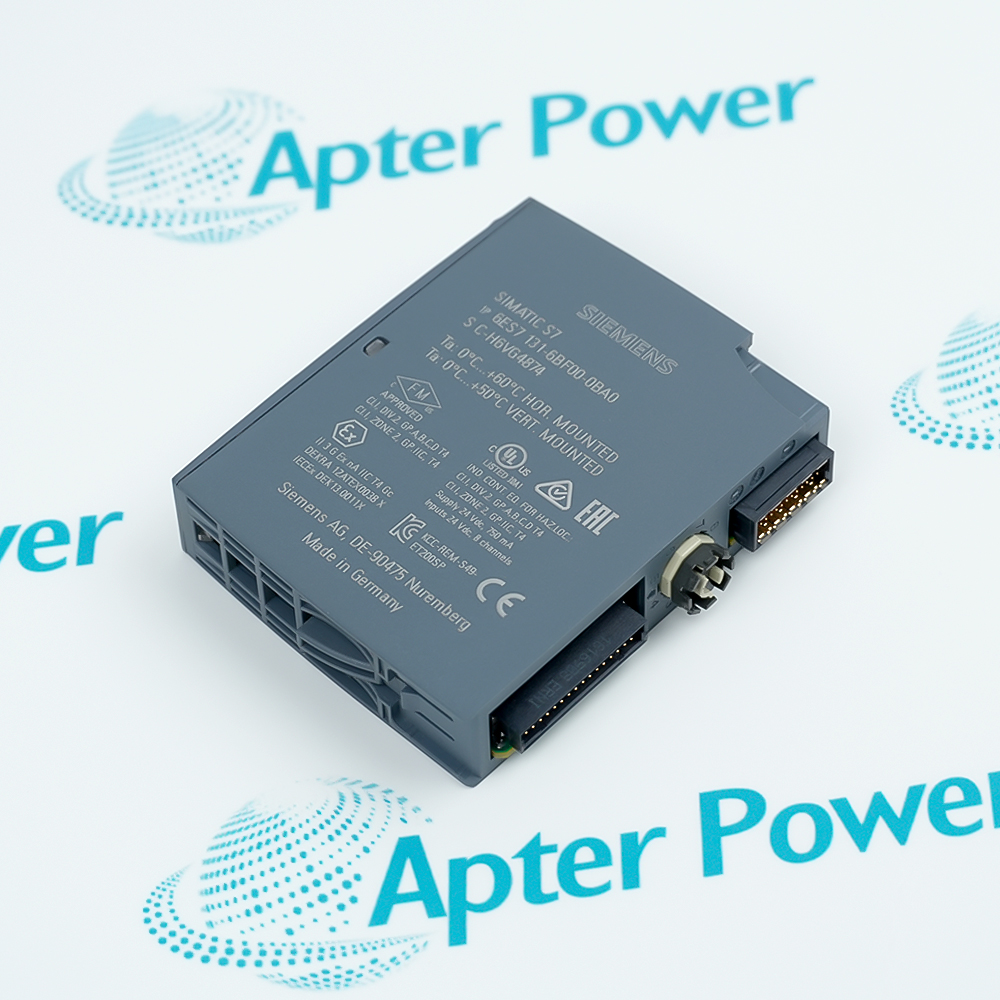
The Siemens 6ES7288-1ST30-0AA1 is a SIMATIC S7-200 SMART ST30 standard CPU with 18 integrated 24 V DC digital inputs, 12 24 V DC transistor outputs, and 30 KB of program/data memory.
- CPU ST30
- 18 DI 24 V DC; 12 transistor DQ
- 24 V DC nominal; 20.4 to 28.8 V DC permissible
- 30 KB program/data memory
It executes the STEP 7 Micro/WIN SMART user program, reads the 18 onboard binary input signals, and commands 12 field outputs for twelve fast transistor outputs with expanded input capacity for coordinated machine control. Its transistor channels also support the high-speed pulse-output functions documented by Siemens. The standard CPU exchanges engineering, process, and diagnostic data over Industrial Ethernet/PROFINET and RS485, and can use compatible S7-200 SMART expansion components. It is suited to assembly stations and positioning equipment.
Important Notice: Use the complete 6ES7288-1ST30-0AA1 code and verify the physical nameplate, firmware, project, accessories, and current Siemens documentation before installation or replacement.
Apter Power 6ES7288-1ST30-0AA1 Manuals and Guides
Important Notice: These are two separate Apter Power documents prepared from the manufacturer-published Siemens information named in each document. Confirm the physical nameplate, current Siemens documents, and host-system requirements before installation or replacement.
High-speed machine I/O
Reads 18 digital states and switches 12 transistor outputs without relay contact wear
Pulse-train positioning
Generates configured PTO signals for compatible motion components
Packaging and labeling
Coordinates sensors, actuators, and indexed motion in assembly stations and positioning equipment
Networked compact control
Exchanges commands, process values, and diagnostics over the documented interfaces
Read the exact Siemens S7-200 SMART documentation before use. Verify 6ES7288-1ST30-0AA1, CPU ST30, power, I/O wiring, firmware, and project from the physical installation.
1
Identity: Match the complete 6ES7288-1ST30-0AA1 MLFB, CPU ST30 marking, hardware, and firmware
2
Power: Verify 24 V DC nominal; 20.4 to 28.8 V DC permissible and isolate all sources before wiring or removal
3
I/O: Observe every channel voltage, current, group common, polarity, and protective-device limit
4
Project: Back up and match the STEP 7 Micro/WIN SMART configuration, addresses, communications, and retentive data
5
Panel: Use DIN-rail mounting, protective earth, segregation, ventilation, and orientation limits from Siemens


 Videos
 News
News Applications