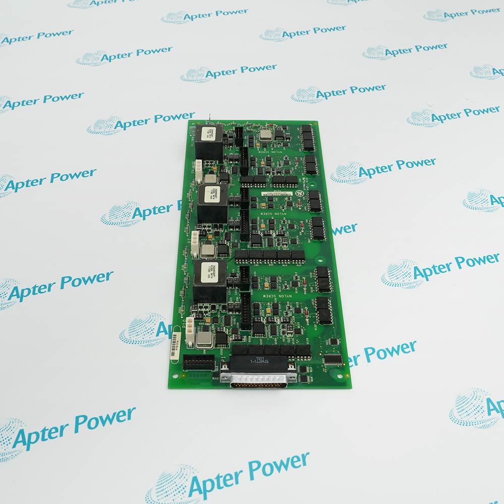
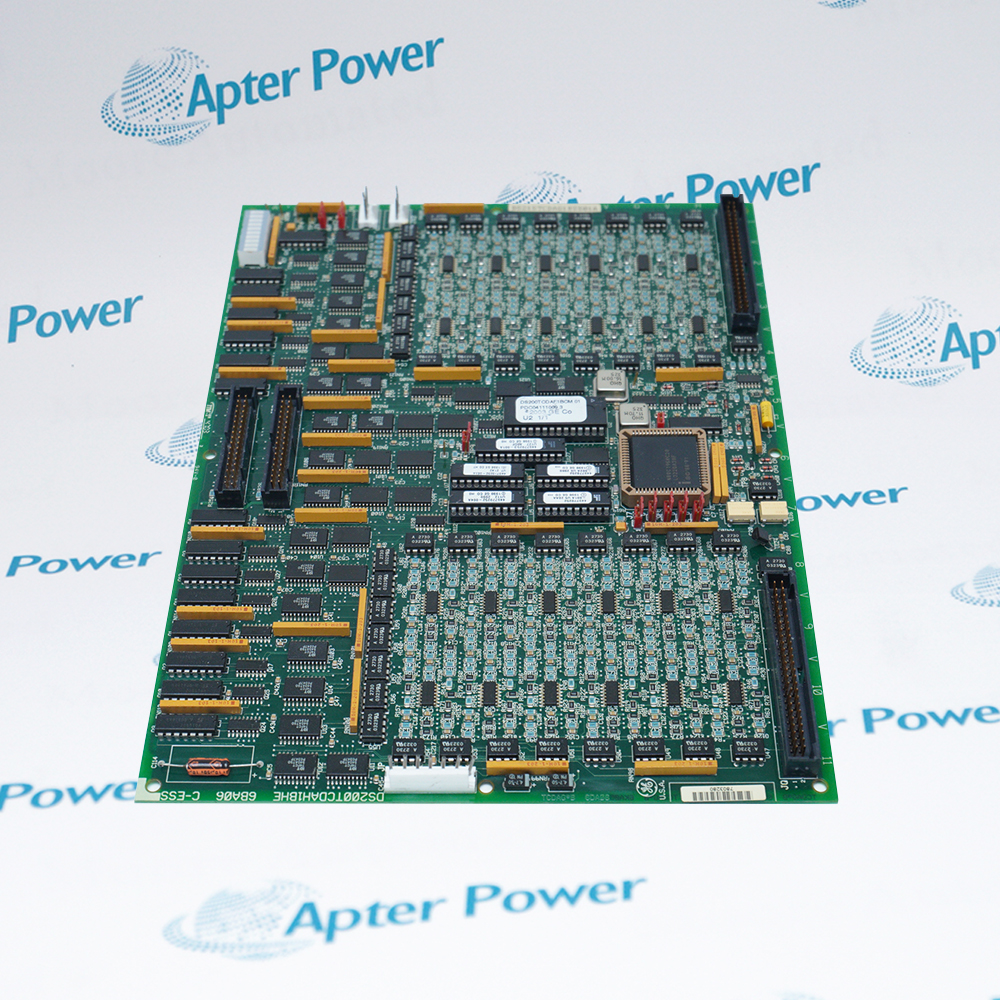
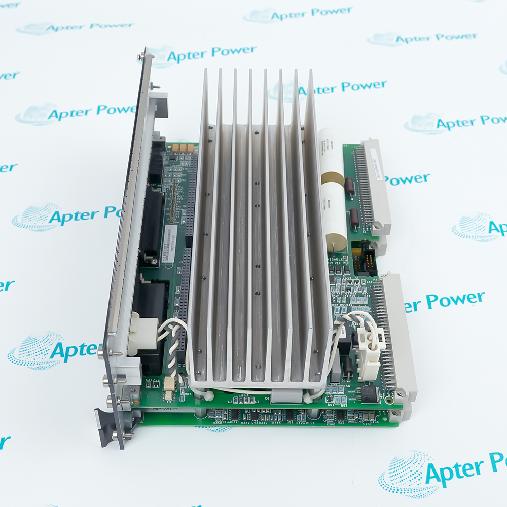
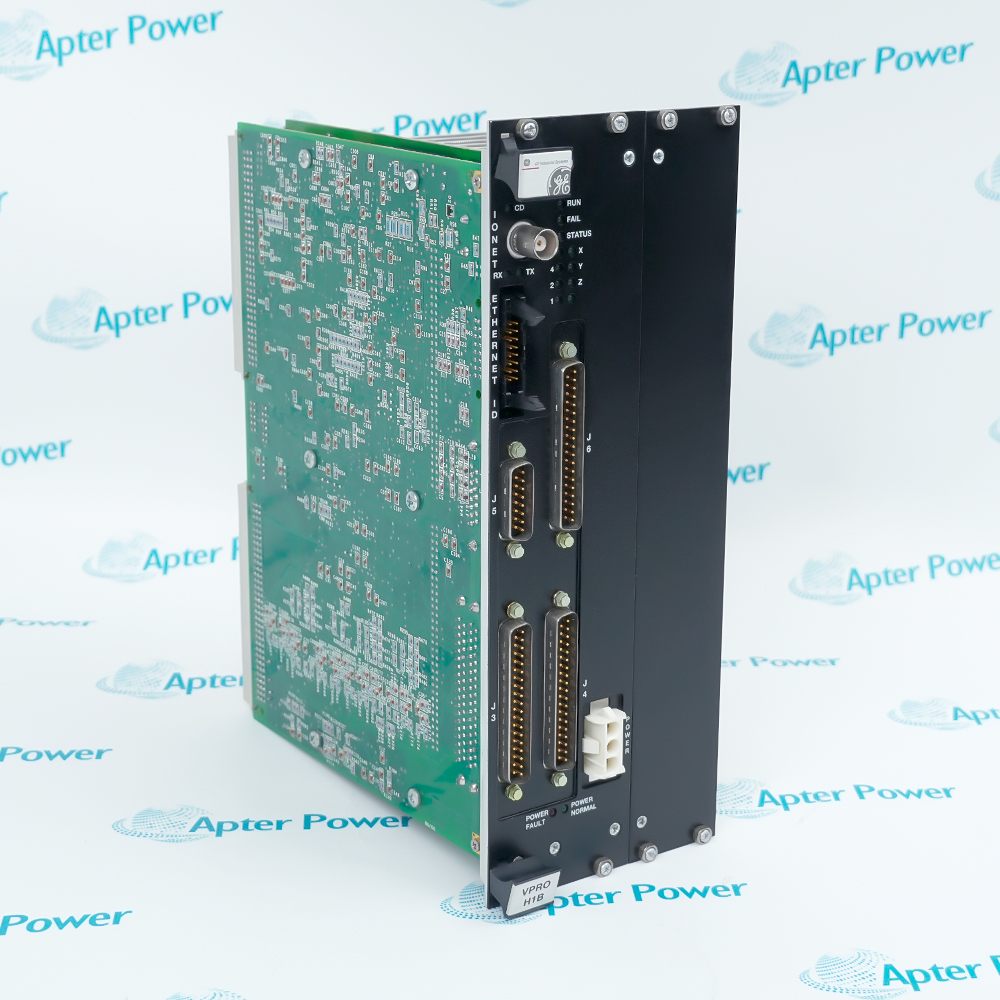
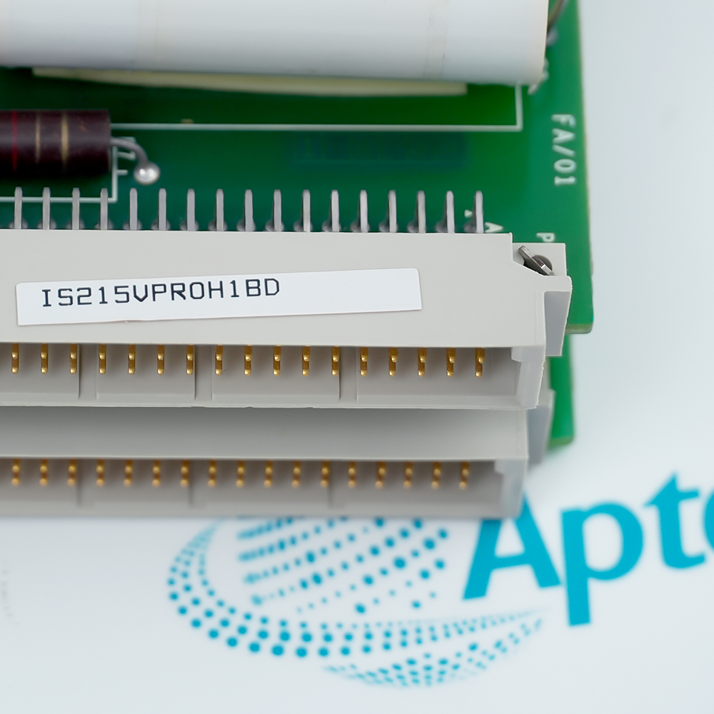
Provides an independent emergency-protection path that remains separate from the normal turbine-control execution path.
- Signal or energy path: Speed, emergency-stop and trip-interlock information is evaluated in the protection architecture, which then coordinates the documented trip-solenoid path through the associated terminal hardware.
- Companion components: The installed protection module must use the approved companion trip terminal boards, speed pickups, emergency-stop circuits and rack connections.
- Engineering check: Verify the complete revision, voting arrangement, trip wiring, pickup calibration and fail-safe response before returning the turbine to service.
- System boundary: Emergency protection remains independent of normal turbine-control execution and must follow the documented trip-terminal architecture.
Emergency overspeed protection and independent shutdown functions for gas- and steam-turbine installations.
Important Notice: Verify the complete IS215VPROH1BD nameplate, installed-system documentation, companion hardware and current GE Vernova instructions before installation or replacement.
Apter Power IS215VPROH1BD Manuals and Guides
Important Notice: The first link is the product-parameters PDF prepared only from the cited manufacturer information; the second link is the Apter Power product manual. Confirm the physical nameplate, current manufacturer documents, and host-system requirements before installation or replacement.
Independent emergency overspeed protection
Three redundant VPRO channels evaluate dedicated speed signals independently from the primary turbine controller.
Voted turbine trip operation
VPRO controls the TREG relay groups that vote trip commands to the turbine trip-solenoid paths.
Emergency-stop and trip-interlock handling
Processes configured hardwired emergency-stop and trip-interlock inputs in the protection module.
Dual-TREG H1B protection arrangements
H1B supports a second TREG through J4 where the unit's trip design requires the additional terminal board.
Read and follow the current GE Vernova documentation and host-equipment instructions before work. Verify the complete physical nameplate and system configuration.
1
Verify the complete IS215VPROH1BD nameplate; do not infer the trailing revision or interchangeability from the VPRO family name.
2
Do not replace H1B with H2B in an application using a second TREG; GEH-6421M says H2B omits the second-TREG function.
3
Treat all work as safety-critical turbine-trip work and follow the unit-specific lockout, replacement, configuration and proof-test procedure.
4
Confirm TPRO, TREG and TRPG board forms, J3/J4/J5/J6 cabling, J7 power, speed-pickup assignment and trip-solenoid circuits before energization.
5
Verify firmware, I/O configuration, overspeed setpoints, emergency-stop logic and relay/solenoid feedback diagnostics against the approved turbine protection design.