Get Parts Quote
Name
Company *
Phone *
Email *
Address
City
State / Province / Region
Zipcode
Country
Quantity *
Part Number *
Manufacturer
Preferred Condition
Additional Information
Cancel

990-10-XX-01-05

Vibration Transmitter
In Stock
Ships by Wednesday, October 14
Fast Shipping Available

Product Describe:

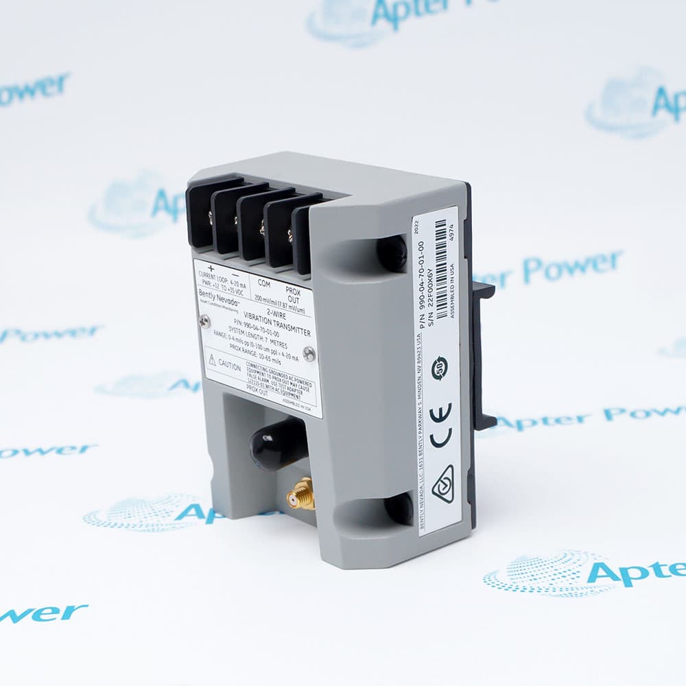
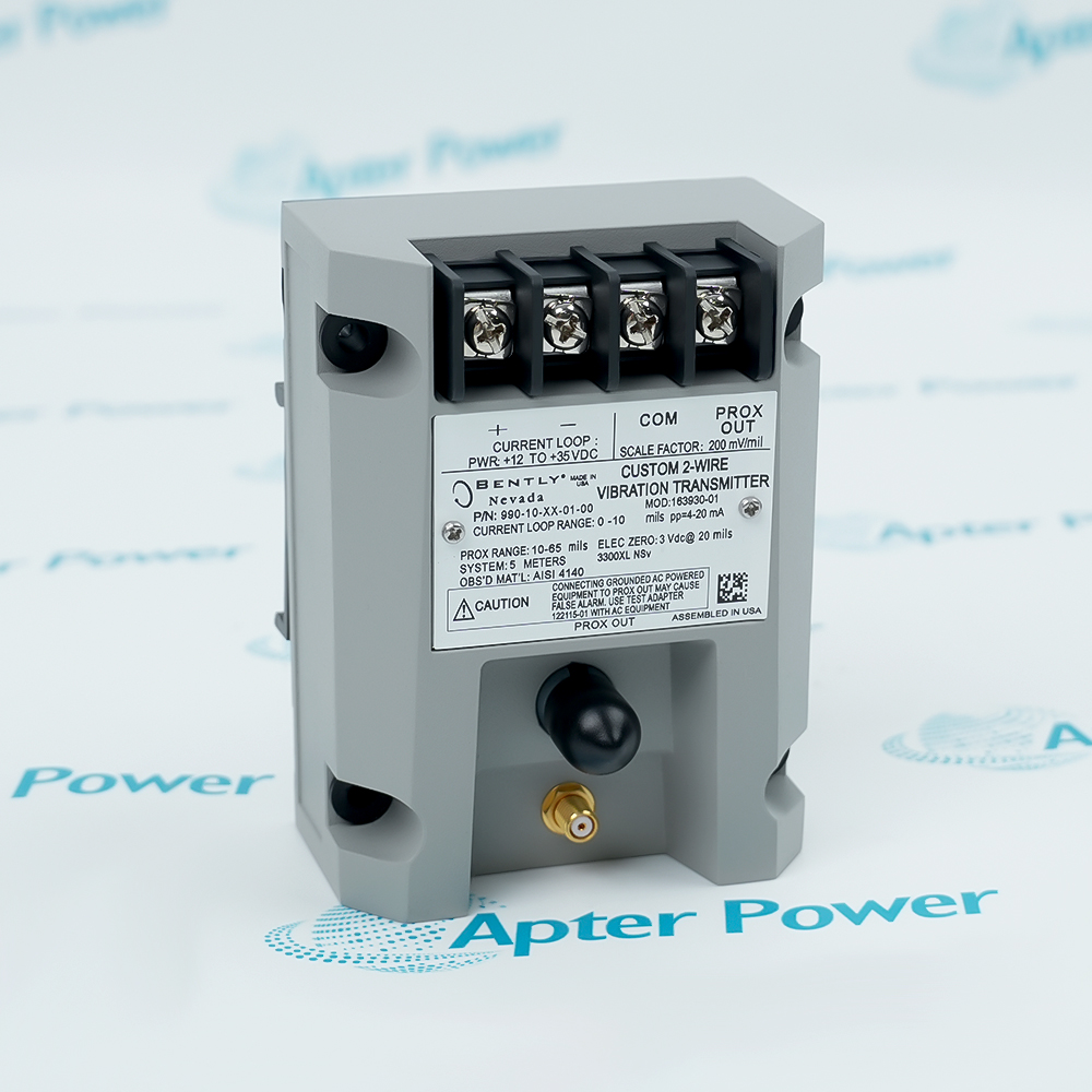
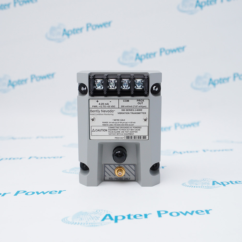
Bently Nevada 990-10-XX-01-05 is a two-wire vibration transmitter with a 0–10 mil peak-to-peak full-scale option and a proportional 4–20 mA output. It uses 35 mm DIN-rail clips with a matched 3300 NSv proximity-probe system.

Ask our team:

Get a quick price for: 990-10-XX-01-05
Quantity*
Upload (gif, jpg, jpeg, png, bmp, doc, docx, xls, xlsx, ppt, pdf, csv)
For more information on how your data is processed and stored by Apterpower please read our privacy policy.

Technical specifications for 990-10-XX-01-05

Technical specifications for 990-10-XX-01-05

  • Manufacturer:
    Bently Nevada
  • Product Category:
    Machinery Monitoring System
  • Spare Part Number:
    990-10-XX-01-05
  • Estimated shipping dimensions:
    7.4×5.8×10cm
  • Weight:
    0.5 kg
  • Tariff Code:
    8537101190
  • Counliy of origin:
    USA
  • Full-scale option:
    0–10 mils pp (0–250 µm pp)
  • Mounting option:
    35 mm DIN rail clips
  • Approval option:
    CSA Div 2; ATEX Zone 0 and 2; ABS maritime
  • Signal output:
    4–20 mA DC, two-wire
  • Supply at transmitter:
    +12 to +35 V DC
  • Sensor input:
    One 3300 NSv probe and extension cable
  • Loop accuracy:
    ±1.5% over full-scale range
  • Maximum loop resistance:
    1,000 Ω including cable at 35 V DC
  • Probe gap for full scale:
    0.5–1.75 mm
  • NOT OK response:
    <3.6 mA within 100 µs
  • PROX OUT impedance:
    10 kΩ, calibrated for 10 MΩ load
  • Operating temperature:
    -35 to +85 °C

Information

Information

Overview Manuals Common Applications Product Precautions
Bently Nevada 990-10-XX-01-05 is a two-wire 990 vibration transmitter for a documented machinery-monitoring loop.
  • 0–10 mil peak-to-peak vibration range
  • XX remains unresolved
  • 35 mm DIN rail mounting selection
  • multi-agency approval option in the final order-code position

The NSv probe, extension cable, transmitter and receiving input form a matched measurement chain. Treat XX as unresolved until the exact selection is documented. Check loop power and the controlled 4–20 mA response before release.

Important Notice: Confirm the full 990-10-XX-01-05 marking, mounting position, cable route and documented channel scaling. Verify the exact XX selection against the physical marking and purchase record.

Bently Nevada 990-10-XX-01-05 Manuals & Downloads
990-10-XX-01-05 Technical Reference (PDF)990-10-XX-01-05 Installation & Commissioning Guide (PDF)

The first PDF records verified 990-family values and the exact ordered identity; the second covers installation checks, commissioning observations and acceptance evidence.

Shaft vibrationTrend radial shaft movement through the configured 0–10 mil peak-to-peak 4–20 mA channel.
Loop integrationConnect the two-wire transmitter to the documented monitoring-system input and loop supply.
Sensor diagnosticsCheck probe gap, cable continuity, NOT OK current behavior and the PROX OUT signal path.
Exact-article maintenanceReplace 990-10-XX-01-05 only after its mount, length selection, approval position and site scaling are checked.
Read the applicable 990 installation instructions before work. Verify 990-10-XX-01-05 and the complete sensing and loop configuration before isolation or commissioning.
1
Confirm the complete 990-10-XX-01-05 nameplate and the installed 990 channel record.
2
Place the machine, protection channel and transmitter loop in the approved maintenance state.
3
Record probe, extension, mounting, terminals, shield and loop assignments before removal.
4
Treat XX as unresolved until the exact selection is documented. Confirm 35 mm DIN rail mounting from the actual installation.
5
Check the +12 to +35 V DC loop supply and receiving-input burden against the installed design.
6
Inspect NSv probe gap, target condition, cable route and connector engagement.
7
Restore wiring and verify 4–20 mA response and NOT OK indication under controlled conditions.
8
Retain exact article identity and as-left acceptance evidence. Verify the exact XX selection against the physical marking and purchase record.

Technical notes

Technical notes

Mount the transmitter with its 35 mm DIN-rail clips and verify the installed NSv probe/extension-cable system before adjustment. Confirm the probe gap and current-loop response during commissioning.

FAQS

  • What full-scale engineering span belongs to the 10 option?
    For 990-10-XX-01-05, the 10 option represents 0–10 mils peak-to-peak, equivalent to 0–250 µm pp.
  • Which mechanical support corresponds to its 01 mounting code?
    The 01 code calls for 35 mm DIN-rail clips; do not substitute the separate bulkhead-screw option.
  • Why must the NSv probe and extension cable be treated as a matched system?
    The transmitter conditions a signal from one 3300 NSv proximity probe and its matching extension cable. Their installed configuration determines the measurement path.
  • What do the PROX OUT and COM terminals provide?
    They expose a non-isolated dynamic transducer and gap-voltage signal for diagnostics, separate from the proportional 4–20 mA loop.
  • Why is 4 mA not the same as a NOT OK indication?
    A valid zero-scale output is around 4 mA; a NOT OK condition drives the transmitter below 3.6 mA within 100 µs.
  • What measurement does a 4–20 mA PLC input receive?
    It receives proportional peak-to-peak vibration amplitude over the selected 0–10 mil range, not phase or a complete dynamic waveform.
  • When are zero and span controls adjusted?
    Use the non-interacting external controls during controlled loop verification after the probe has been gapped and the system is connected.
  • Which approvals are included by the 05 ending?
    The 05 option includes CSA Division 2, ATEX Zone 0 and Zone 2, and ABS maritime approval for the ordered transmitter execution.
Trusted by 5,000+ plants worldwide | Backed by our vast inventory of top-tier control parts, modules and cards, fast shipments are dispatched to cover your urgent needs. ABOUT US >>
Disclaimer: We are not an authorized distributor or distributor of the product manufacturer of this website, The product may have older date codes or be an older series than that available direct from the factory or authorized dealers. Because our company is not an authorized distributor of this product, the Original Manufacturer`s warranty does not apply.While many DCS PLC products will have firmware already installed, Our company makes no representation as to whether a DSC PLC product will or will not have firmware and, if it does have firmware, whether the firmware is the revision level that you need for your application. Our company also makes no representations as to your ability or right to download or otherwise obtain firmware for the product from our company, its distributors, or any other source. Our company also makes no representations as to your right to install any such firmware on the product. Our company will not obtain or supply firmware on your behalf. It is your obligation to comply with the terms of any End-User License Agreement or similar document related to obtaining or installing firmware.

We’re Here When You Need Us

From product insights to customer service needs, our experienced service team will focus on getting you what you need quickly

Enquire

Complete our online form.

Call Us

Speak to one of our team.

Live Chat

Send us a message.