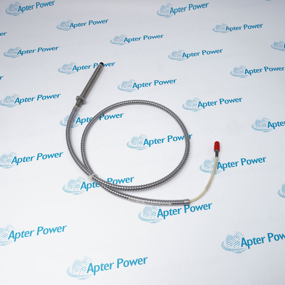
The 74712-03-11-02-00 is a Bently Nevada 74712 high-temperature two-wire Seismoprobe velocity transducer calibrated for 90 +/-2.5 degrees from vertical, with a 4.5 Hz minimum operating frequency, an isolated circular M10 x 1 mounting base, a top-mount connector, and no agency approval option.
- 90 +/-2.5 degrees
- 4.5 Hz (270 cpm)
- 4.5 to 1000 Hz, +0/-3 dB typical for this option
- 20 mV/mm/s (500 mV/in/s), +/-5%
Mounted on a bearing housing or machine casing, its internal seismic mechanism produces a voltage proportional to casing vibration velocity. The two-wire signal is routed through a compatible high-temperature cable to a Bently Nevada monitor or vibration data-collection input for continuous condition monitoring of rotating equipment. For dependable operation, follow the official system-matching, mounting, wiring, environmental, and approval instructions.
Important Notice: Preserve the ordered 90-degree orientation, rigid M10 x 1 mounting, top connector clearance, compatible high-temperature cable, 10 kohm load, and option-00 approval status.
Apter Power 74712-03-11-02-00 Manuals and Guides
Important Notice: These are two separate Apter Power documents prepared from the official Bently Nevada source named in each document. Confirm the physical nameplate, current manufacturer documentation, and applicable installation drawing before installation or replacement.
Steam Turbine Casings
Measures absolute casing vibration at elevated temperatures.
Gas Turbine Bearings
Monitors bearing-housing velocity where a high-temperature sensor is required.
Compressors
Tracks structural vibration transmitted to the machine case.
Large Pumps
Supports continuous velocity monitoring at bearing housings.
Fans and Blowers
Measures housing vibration for balance and mechanical-condition assessment.
Protected Enclosures
Standard installation uses a protected enclosure with field wiring in conduit.
Read and follow the official manufacturer source and applicable installation instructions before use. Verify the exact complete ordering code from the physical nameplate.
1
Install the transducer at 90 +/-2.5 degrees from vertical as viewed from the driver end of the machine.
2
Prepare a rigid flat mounting surface and tighten the M10 x 1 base to the published 5.6 N m torque.
3
Route the separate high-temperature cable in protected conduit and keep connections dry and mechanically supported.
4
Use a 10 kohm compatible input and verify polarity, shielding, frequency response, and channel scaling.
5
Do not infer hazardous-area certification: final option 00 orders no agency approval.


 Videos
 News
News Applications