Get Parts Quote
Name
Company *
Phone *
Email *
Address
City
State / Province / Region
Zipcode
Country
Quantity *
Part Number *
Manufacturer
Preferred Condition
Additional Information
Cancel

3500/25-SIL2-02-01-01

Enhanced Keyphasor module / four-channel SIL2 ordering configuration
In Stock
Ships by Wednesday, October 7
Fast Shipping Available

Product Describe:

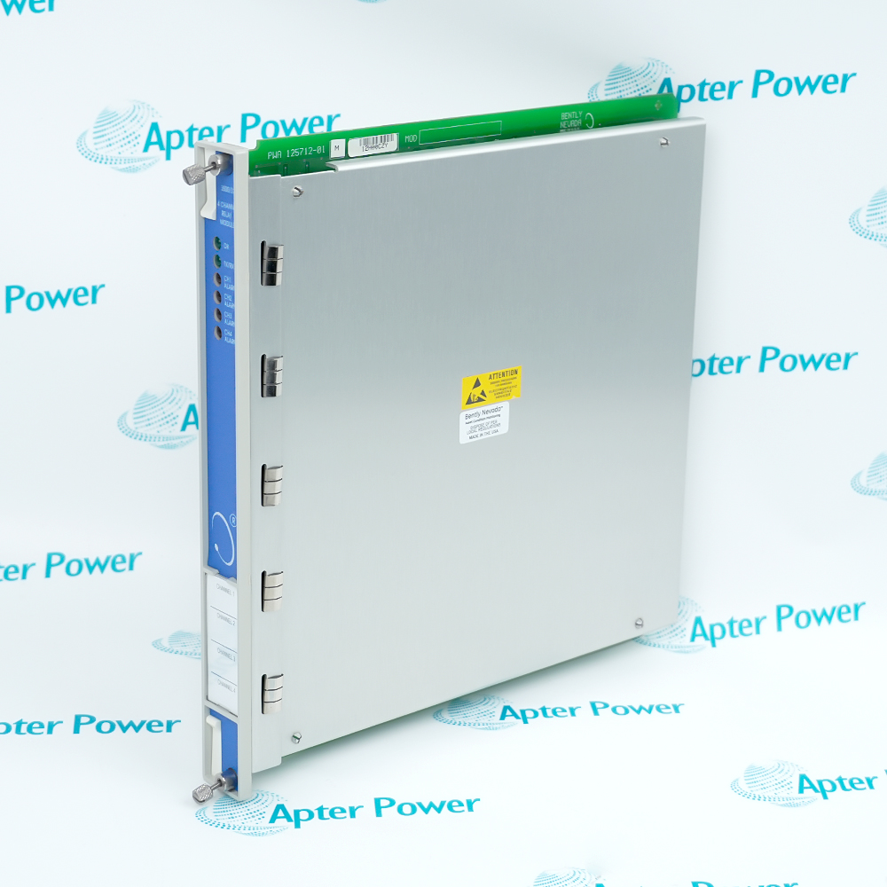
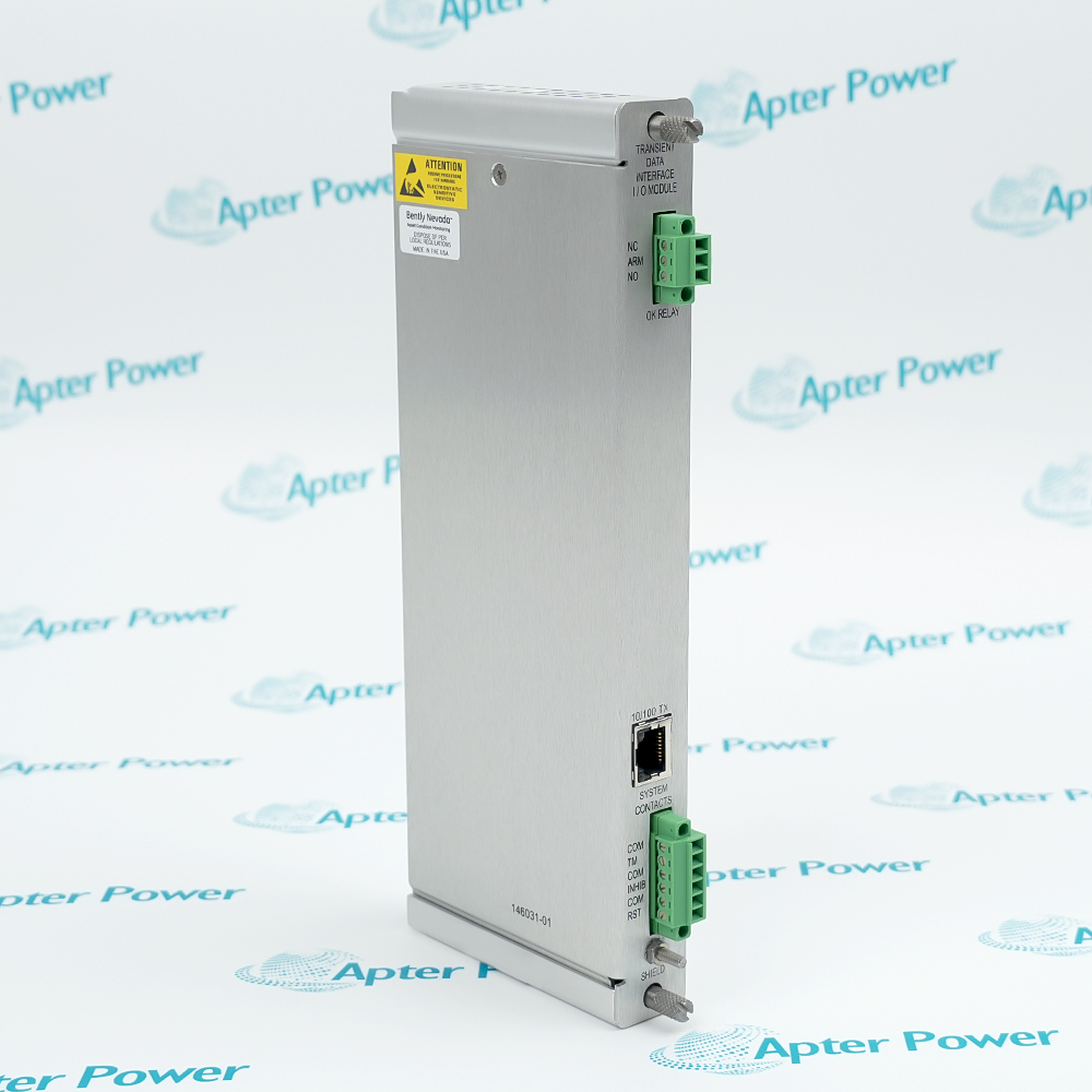
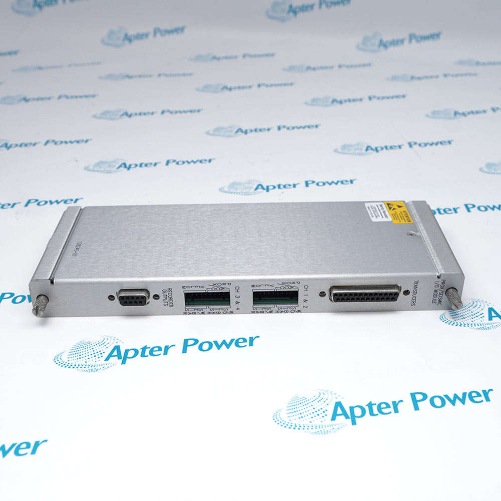
Bently Nevada 3500/25-SIL2-02-01-01 is the documented enhanced keyphasor module / four-channel sil2 ordering configuration for the 25 product family. Bently Nevada 3500/25-SIL2-02-01-01 combines two half-height Enhanced Keyphasor cards with internal-termination I/O for four phase-reference channels in a 3500 machinery-protection rack.

Ask our team:

Get a quick price for: 3500/25-SIL2-02-01-01
Quantity*
Upload (gif, jpg, jpeg, png, bmp, doc, docx, xls, xlsx, ppt, pdf, csv)
For more information on how your data is processed and stored by Apterpower please read our privacy policy.

Technical specifications for 3500/25-SIL2-02-01-01

Technical specifications for 3500/25-SIL2-02-01-01

  • Manufacturer:
    Bently Nevada
  • Product Category:
    Machinery Monitoring System
  • Spare Part Number:
    3500/25-SIL2-02-01-01
  • Estimated shipping dimensions:
    2.5x25.6x24cm
  • Weight:
    0.8 kg
  • Tariff Code:
    8537101190
  • Counliy of origin:
    USA
  • Ordering configuration:
    02 / two half-height 2-channel cards; 01 internal-termination I/O; 01 cNRTLus Class I, Division 2
  • Input signal:
    Proximity probe or magnetic pickup
  • Power consumption:
    3.2 W typical per module
  • Non-isolated input range:
    +0.8 to -21 V
  • Input impedance:
    21.8 kOhm minimum
  • Input frequency:
    1 to 1,200,000 cpm
  • Output speed range:
    1 to 99,999 cpm
  • Automatic threshold:
    2 V p-p minimum; 120 rpm minimum
  • Manual threshold:
    0 to -20 Vdc; 0.5 V p-p minimum
  • Trigger hysteresis:
    0.2 to 2.5 V
  • Transducer supply:
    -24 Vdc nominal, 40 mA per channel
  • Operating temperature:
    -30 to +65 degrees C without barriers
  • Storage temperature:
    -40 to +85 degrees C
  • Relative humidity:
    95%, non-condensing
  • Rack space:
    One half-height front slot per card; one full rear slot per I/O module

Information

Information

Overview Manuals Common Applications Product Precautions
Bently Nevada 3500/25-SIL2-02-01-01 is the documented enhanced keyphasor module / four-channel sil2 ordering configuration for the 25 product family.
  • Accepts proximity-probe or magnetic-pickup phase reference inputs.
  • Processes four channels through two half-height two-channel cards.
  • Supports automatic or manual trigger thresholds and keyed event outputs.
  • Provides buffered phase signals for speed and vector measurements in the rack.

Install 3500/25-SIL2-02-01-01 as the documented two-card, four-channel Keyphasor arrangement with its internal-termination I/O modules. Commissioning covers input waveform, trigger level, polarity, phase stability and speed indication.

Important Notice: Confirm the complete 3500/25-SIL2-02-01-01 identity, installed interfaces, approved configuration and final functional acceptance record before service release.

3500/25-SIL2-02-01-01 Manuals & Downloads
3500/25-SIL2-02-01-01 Technical Reference (PDF)3500/25-SIL2-02-01-01 Installation & Commissioning Guide (PDF)

Important Notice: The first document presents exact-model technical data and engineering questions. The second provides a separate model-specific installation, configuration and acceptance workflow.

Four-channel phase reference
Provide independent keyed phase inputs for machines needing multiple shaft-reference channels.
Speed-related measurements
Supply phase timing used by compatible 3500 monitors for speed and vector calculations.
Proximity-probe triggering
Use a keyed shaft surface with the documented proximity-probe input envelope.
Magnetic-pickup triggering
Use compatible passive pickup signals when the minimum amplitude and speed conditions are met.
Read the applicable Bently Nevada installation instructions before work. Verify 3500/25-SIL2-02-01-01, its installed system arrangement and configured interfaces before commissioning.
1
Confirm both half-height cards and both internal-termination I/O assemblies match the complete ordering configuration.
2
Match each channel to its documented proximity probe or magnetic pickup before energizing the rack.
3
Set automatic or manual trigger thresholds from an observed waveform, not from an assumed keyway amplitude.
4
Keep the non-isolated input within +0.8 to -21 V and preserve the rack grounding plan.
5
Verify keyed-event polarity and hysteresis before using phase in protection or diagnostic measurements.
6
Check the configured input frequency and the reported speed over a controlled run-up.
7
Protect the rear internal-termination wiring and confirm the correct half-height slot assignment.
8
Record final trigger level, phase stability, speed indication and channel OK state before release.

Technical notes

Technical notes

Confirm both half-height cards and both internal-termination I/O assemblies match the complete ordering configuration. Record final trigger level, phase stability, speed indication and channel OK state before release.

FAQS

  • How do the two half-height cards in 3500/25-SIL2-02-01-01 provide four Keyphasor channels?
    The 02 monitor option specifies two two-channel half-height Enhanced Keyphasor cards, so the rack arrangement provides four processed phase-reference inputs.
  • Which transducer signal types can 3500/25-SIL2-02-01-01 accept at its four inputs?
    The datasheet permits proximity-probe signals and magnetic-pickup signals; the installed channel configuration and signal amplitude must match the selected type.
  • What input-frequency envelope should be checked for 3500/25-SIL2-02-01-01 during commissioning?
    The specified input range is 1 to 1,200,000 cpm, while the processed output speed range is 1 to 99,999 cpm.
  • When may 3500/25-SIL2-02-01-01 use automatic trigger threshold selection?
    Automatic threshold operation requires at least 2 V peak-to-peak input and at least 120 rpm; otherwise use a verified manual threshold.
  • What manual trigger limits apply when configuring 3500/25-SIL2-02-01-01?
    The published manual threshold range is 0 to -20 Vdc with a 0.5 V peak-to-peak minimum input signal.
  • How should trigger hysteresis be verified for 3500/25-SIL2-02-01-01?
    Use the configurable 0.2 to 2.5 V hysteresis range and verify stable keyed events without chatter over the operating waveform.
  • What rear termination arrangement belongs with 3500/25-SIL2-02-01-01?
    The 01 I/O option is the internal-termination module; verify both rear I/O assemblies and the corresponding half-height front-card positions.
  • Which release checks establish a usable phase reference from 3500/25-SIL2-02-01-01?
    Confirm channel OK state, stable keyed-event polarity, consistent phase, correct speed indication and repeatable triggering through a controlled run-up.
Trusted by 5,000+ plants worldwide | Backed by our vast inventory of top-tier control parts, modules and cards, fast shipments are dispatched to cover your urgent needs. ABOUT US >>
Disclaimer: We are not an authorized distributor or distributor of the product manufacturer of this website, The product may have older date codes or be an older series than that available direct from the factory or authorized dealers. Because our company is not an authorized distributor of this product, the Original Manufacturer`s warranty does not apply.While many DCS PLC products will have firmware already installed, Our company makes no representation as to whether a DSC PLC product will or will not have firmware and, if it does have firmware, whether the firmware is the revision level that you need for your application. Our company also makes no representations as to your ability or right to download or otherwise obtain firmware for the product from our company, its distributors, or any other source. Our company also makes no representations as to your right to install any such firmware on the product. Our company will not obtain or supply firmware on your behalf. It is your obligation to comply with the terms of any End-User License Agreement or similar document related to obtaining or installing firmware.

We’re Here When You Need Us

From product insights to customer service needs, our experienced service team will focus on getting you what you need quickly

Enquire

Complete our online form.

Call Us

Speak to one of our team.

Live Chat

Send us a message.