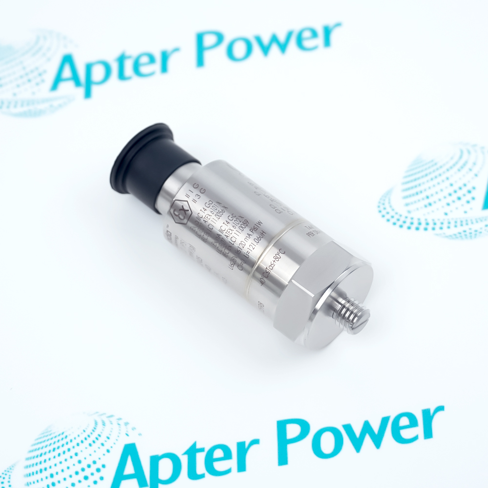
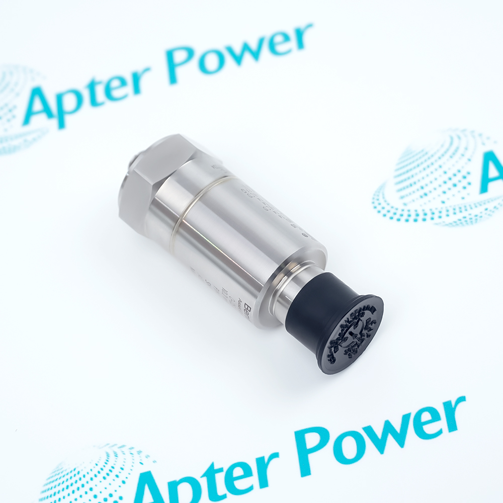
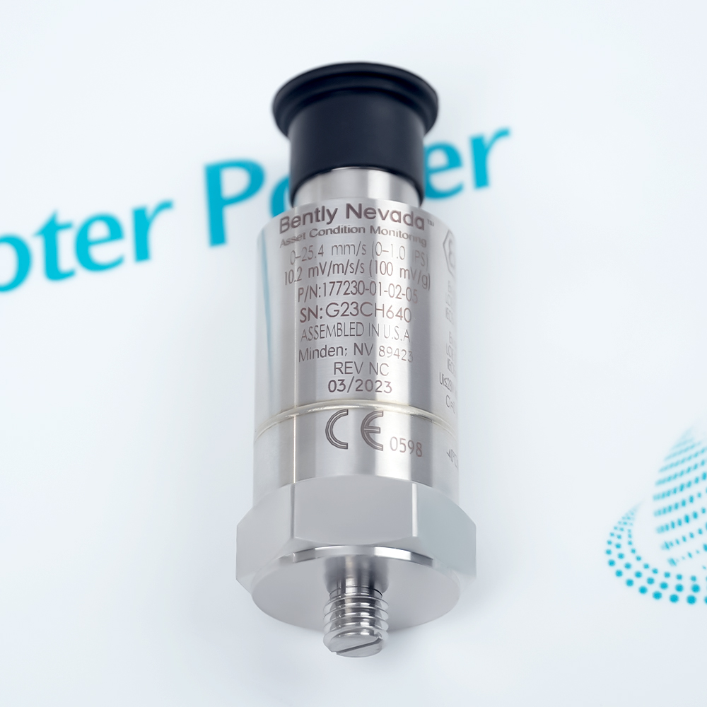
The 177230-01-02-05 is a Bently Nevada self-contained piezoelectric seismic transmitter with a 0 to 25.4 mm/s (0 to 1.0 in/s) velocity range, 3 Hz to 1 kHz frequency option, 4 to 20 mA primary velocity output, secondary unbuffered acceleration output, and multiple approvals.
- Self-contained piezoelectric seismic transmitter
- 4 to 20 mA current loop
- 0 to 25.4 mm/s (0 to 1.0 in/s)
- 3 Hz to 1 kHz
It senses casing or bearing-housing vibration on general-purpose machinery, converts the measured velocity level to a proportional two-wire 4 to 20 mA signal for PLC, DCS, or SCADA input, and provides a secondary dynamic acceleration signal for diagnostic verification. The 3 Hz to 1 kHz option reports peak vibration level. For dependable measurement, follow official system-matching, target, mounting, wiring, environmental, and approval instructions.
Important Notice: Confirm the analog input scaling, output basis, wiring, mounting torque, and approval entity parameters before commissioning.
Apter Power 177230-01-02-05 Product Manual
Important Notice: This Apter Power manual is prepared from the manufacturer source identified on the product page. Confirm the physical nameplate, current original-manufacturer documents, and applicable certification before installation or replacement.
Electric MotorsMonitors bearing-housing vibration on general-purpose motors.
PumpsProvides a 4 to 20 mA vibration input for pump condition monitoring.
Small Reciprocating CompressorsMeasures casing vibration where accelerometer-based monitoring is appropriate.
PLC and DCS InputsFeeds a proportional vibration signal to machinery control systems.
SCADA MonitoringSupports remote trending of general-purpose machine vibration.
Diagnostic VerificationUses the secondary acceleration output for waveform or spectrum analysis.
Read and follow Bently Nevada 177230 Seismic Transmitter Datasheet 177232 Rev. T and the applicable installation instructions before use. Verify the exact ordering code from the physical nameplate.
1Mount directly by stud where practical and tighten to the published 4 to 7 N-m torque.
2If using a magnetic base, roll it onto the machine; do not snap it into place because the resulting shock can damage the electronics.
3Use shielded three-conductor wiring and follow the published pin assignments and loop-power limits.
4Confirm the analog input scaling matches the ordered range and output basis.
5Verify the 05 approval marking, entity parameters, cable parameters, and installation drawing before hazardous-area use.