











Get Parts Quote
Name
Company *
Phone *
Email *
Address
City
State / Province / Region
Zipcode
Country
Quantity *
Part Number *
Manufacturer
Preferred Condition
Additional Information
Cancel
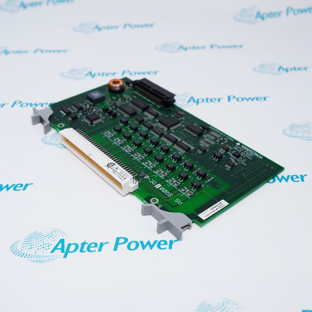
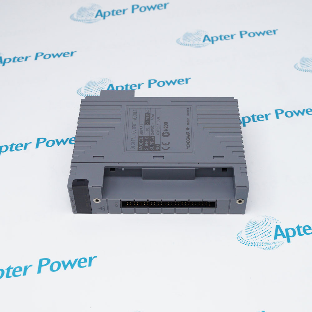
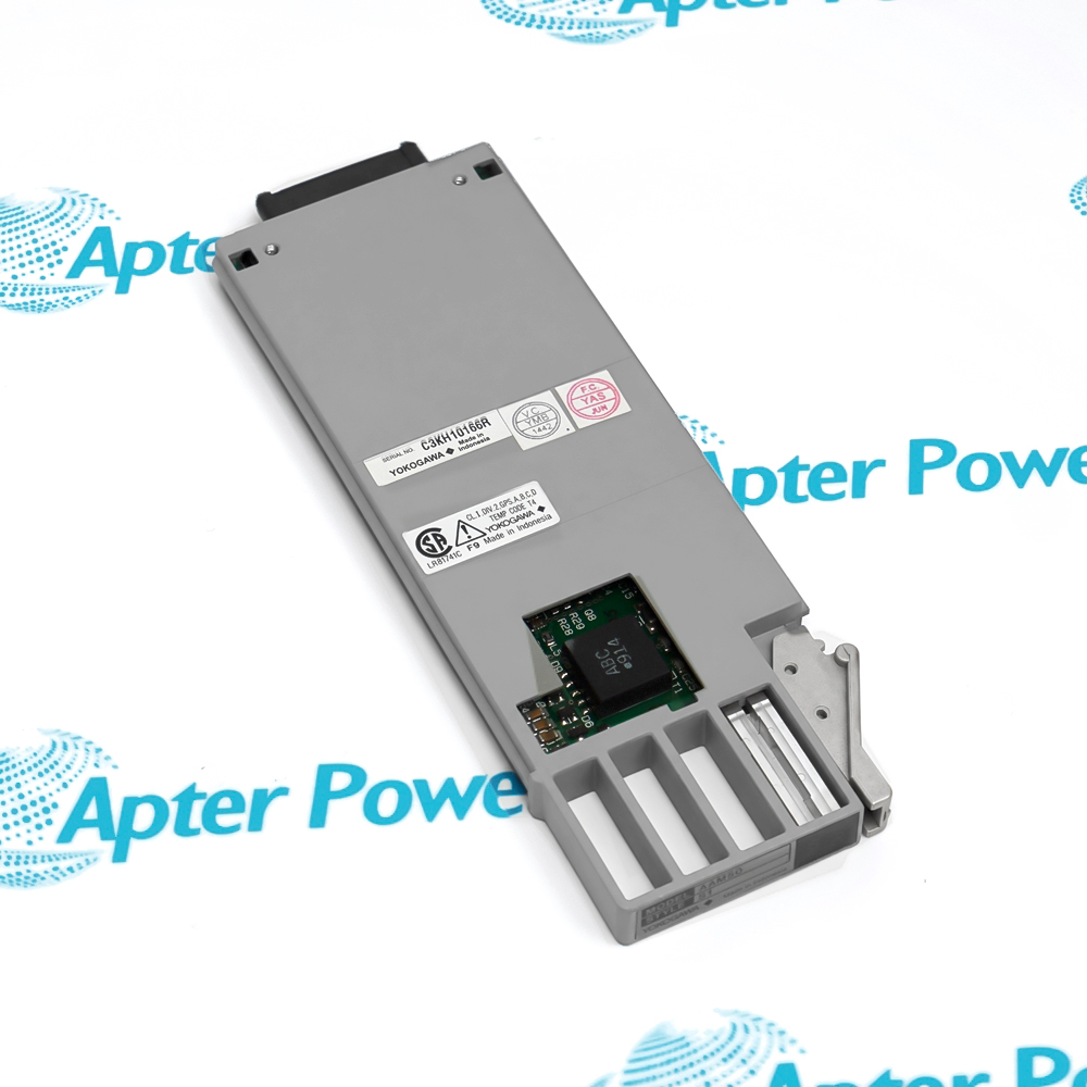
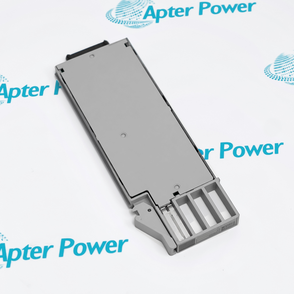
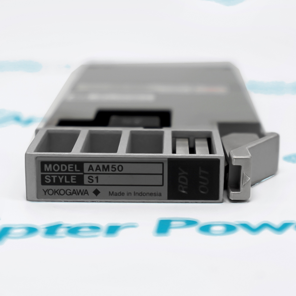
Yokogawa AAM50
Yokogawa AAM50
Yokogawa AAM50
Yokogawa AAM50
Yokogawa AAM50
Yokogawa AAM50
Product image is representative; revision or series may vary. Contact us to request a specific version.

AAM50

Current Output Module
In Stock
Ships by Wednesday, October 14
Fast Shipping Available

Product Describe:

Yokogawa AAM50 is a 4 to 20 mA DC current output module for an analog I/O module nest. It drives loads up to 750 ohms and updates output data every 20 ms.

Ask our team:

Get a quick price for: AAM50
Quantity*
Upload (gif, jpg, jpeg, png, bmp, doc, docx, xls, xlsx, ppt, pdf, csv)
For more information on how your data is processed and stored by Apterpower please read our privacy policy.

Technical specifications for AAM50

Technical specifications for AAM50

  • Manufacturer:
    Yokogawa
  • Product Category:
    DCS System
  • Spare Part Number:
    AAM50
  • Estimated shipping dimensions:
    16.6x5.8x1.1cm
  • Weight:
    0.08 kg
  • Tariff Code:
    8537101190
  • Counliy of origin:
    Japan
  • Output signal:
    4 to 20 mA DC
  • Output resistance:
    500 kOhm or more
  • Allowable load:
    0 to 750 Ohm
  • Output range:
    1.0 to 21.5 mA DC
  • Output voltage limit:
    25.5 V DC or less
  • Open-output detection:
    0.65 mA or less
  • Accuracy:
    +/-48 microampere
  • Temperature effect:
    +/-32 microampere per 10 degC change
  • Load-change effect:
    +/-16 microampere for 0 to 75 Ohm change
  • Data update:
    20 ms
  • Step response:
    100 ms
  • Current consumption:
    250 mA or less at 5 V DC
  • Isolation withstand:
    1500 V AC for one minute
  • Installation:
    Analog I/O module nest; M4 terminal wiring
  • Software requirement:
    System software R2.07 or later

Information

Information

Overview Manuals Common Applications Product Precautions
Yokogawa AAM50 is Current Output Module. It generates a software-configured 4–20 mA process output from a Yokogawa analog I/O module nest.
  • Provides a 4–20 mA DC output
  • Drives loads up to 750 ohms
  • Updates output data every 20 ms
  • Insulates the output signal from the system

AAM50 operates with Yokogawa AMN11 or AMN12 analog I/O nest, M4 terminal field wiring, configured current-loop receiver, system software R2.07 or later.

Engineered applications include Valve-position current command, DCS analog setpoint output, Recorder or indicator current loop, AAM50 module replacement.

Important Notice: Verify nest position, loop polarity, receiver load, configured output range and software revision; test the loop at controlled values before enabling automatic control.

Yokogawa AAM50 Manuals & Downloads
Yokogawa AAM50 Technical Reference (PDF)Yokogawa AAM50 Installation & Commissioning Guide (PDF)

Important Notice: The first document presents exact-model technical and engineering data. The second provides a separate installation, connection, commissioning and acceptance workflow.


Valve-position current command
Commands a current-loop final control element.
DCS analog setpoint output
Publishes a configured DCS analog setpoint.
Recorder or indicator current loop
Drives a compatible current receiver or recorder.
AAM50 module replacement
Restores the exact current-output position.
Read the applicable Yokogawa instructions before work. Verify AAM50 and the installed Yokogawa process I/O module-nest system configuration.
1
Verify the complete AAM50 marking and its assigned Yokogawa process I/O module-nest system position before work.
2
Place the connected valve-position current command process in the approved maintenance state.
3
Isolate applicable power and one isolated 4 to 20 mA DC process output field energy before disconnection.
4
Record every connector, conductor, address, firmware and software identity before removal.
5
Use ESD controls and protect keyed interfaces, exposed contacts and electronic assemblies.
6
Confirm the installed Yokogawa AMN11 or AMN12 analog I/O nest and M4 terminal field wiring against the approved project.
7
Restore power in a controlled sequence and review device, network and host diagnostics.
8
Prove the intended DCS analog setpoint output function and retain the final test result.

Technical notes

Technical notes

Official-source basis: Yokogawa Process I/O Module Nest General Specifications, GS 33G06K40-01E, 17th Edition. Verify the complete model and installed system configuration before work.

FAQS

  • What current signal does an AAM50 generate?
    It provides a 4 to 20 mA DC process output with a documented usable output range of 1.0 to 21.5 mA.
  • For AAM50, which receiver load is permitted on the current loop?
    The allowable load is 0 to 750 ohms, with an output-voltage limit of 25.5 VDC or less; verify the complete loop burden before connection.
  • For AAM50, how does the module indicate an open output circuit?
    The documented open-output detection level is 0.65 mA or less, so an open loop must be investigated before the point is accepted.
  • For AAM50, what response timing should be expected during a loop test?
    Output data is updated every 20 ms and the documented step response is 100 ms; allow for these values when evaluating a commanded change.
  • For AAM50, which accuracy effects should be considered during calibration?
    The specification lists accuracy of +/-48 microampere, temperature effect of +/-32 microampere per 10 degC and load-change effect of +/-16 microampere for a 0 to 75 ohm change.
  • For AAM50, what isolation check is documented for the analog output?
    The output insulation withstand is 1500 VAC for one minute; preserve the intended isolation boundary between the field loop and the system.
  • Which nest, terminals and software revision support AAM50?
    Install it in an AMN11 or AMN12 analog I/O module nest with M4 terminal wiring and system software R2.07 or later.
  • For AAM50, how should the current-output point be commissioned?
    Verify nest position, loop polarity and receiver load, then command controlled values across the range, confirm open-loop diagnostics and prove the final control or indication response.
Trusted by 5,000+ plants worldwide | Backed by our vast inventory of top-tier control parts, modules and cards, fast shipments are dispatched to cover your urgent needs. ABOUT US >>
Disclaimer: We are not an authorized distributor or distributor of the product manufacturer of this website, The product may have older date codes or be an older series than that available direct from the factory or authorized dealers. Because our company is not an authorized distributor of this product, the Original Manufacturer`s warranty does not apply.While many DCS PLC products will have firmware already installed, Our company makes no representation as to whether a DSC PLC product will or will not have firmware and, if it does have firmware, whether the firmware is the revision level that you need for your application. Our company also makes no representations as to your ability or right to download or otherwise obtain firmware for the product from our company, its distributors, or any other source. Our company also makes no representations as to your right to install any such firmware on the product. Our company will not obtain or supply firmware on your behalf. It is your obligation to comply with the terms of any End-User License Agreement or similar document related to obtaining or installing firmware.

We’re Here When You Need Us

From product insights to customer service needs, our experienced service team will focus on getting you what you need quickly

Enquire

Complete our online form.

Call Us

Speak to one of our team.

Live Chat

Send us a message.
