











Get Parts Quote
Name
Company *
Phone *
Email *
Address
City
State / Province / Region
Zipcode
Country
Quantity *
Part Number *
Manufacturer
Preferred Condition
Additional Information
Cancel

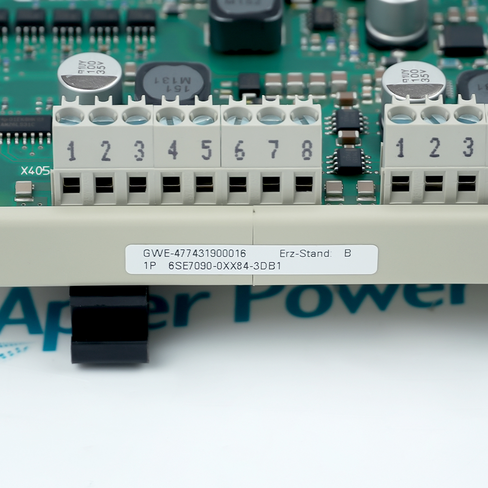
6SE7090-0XX84-3DB1

SIMOVERT MASTERDRIVES Digital Tacho Interface Board
In Stock
Ships by Sunday, September 13
Fast Shipping Available

Product Describe:

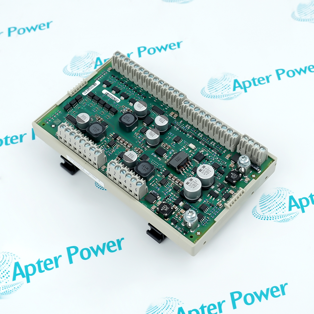
Siemens 6SE7090-0XX84-3DB1 is a SIMOVERT MASTERDRIVES DTI digital tachometer interface board. It accepts isolated TTL or HTL encoder signals and passes conditioned tachometer tracks to the connected drive control or synchronization board.

Ask our team:

Get a quick price for: 6SE7090-0XX84-3DB1
Quantity*
Upload (gif, jpg, jpeg, png, bmp, doc, docx, xls, xlsx, ppt, pdf, csv)
For more information on how your data is processed and stored by Apterpower please read our privacy policy.

Technical specifications for 6SE7090-0XX84-3DB1

Technical specifications for 6SE7090-0XX84-3DB1

  • Manufacturer:
    Siemens
  • Product Category:
    General Automation
  • Spare Part Number:
    6SE7090-0XX84-3DB1
  • Estimated shipping dimensions:
    16x9.8x4.5cm
  • Weight:
    0.28 kg
  • Tariff Code:
    8537101190
  • Counliy of origin:
    Germany
  • Board type:
    DTI digital tachometer interface
  • TTL input:
    5 V
  • HTL input:
    11 to 30 V
  • Input isolation:
    Electrically isolated
  • External supply:
    24 Vdc -16%/+25%
  • HTL supply current:
    300 mA
  • TTL supply current:
    150 mA
  • Digital limit frequency:
    400 kHz
  • TTL terminal:
    X401
  • HTL terminal:
    X402
  • Drive/TSY output:
    X403
  • TTL output:
    X405
  • Conductor range:
    0.5 to 2.5 mm2 inputs
  • Operating temperature:
    0 to 55 deg C
  • Protection degree:
    IP00

Information

Information

Overview Manuals Common Applications Product Precautions
6SE7090-0XX84-3DB1 conditions encoder pulse tracks for a SIMOVERT MASTERDRIVES control path and adds the DB1-specific extended supply capability at X403.6. The board must be matched to the encoder logic level and the installed CU or TSY interface.
  • Interfaces either TTL or HTL digital tachometers
  • Provides electrically isolated encoder inputs
  • Routes conditioned pulse tracks to MASTERDRIVES control hardware
  • Adds the DB1 extended X403.6 supply option for compatible configurations

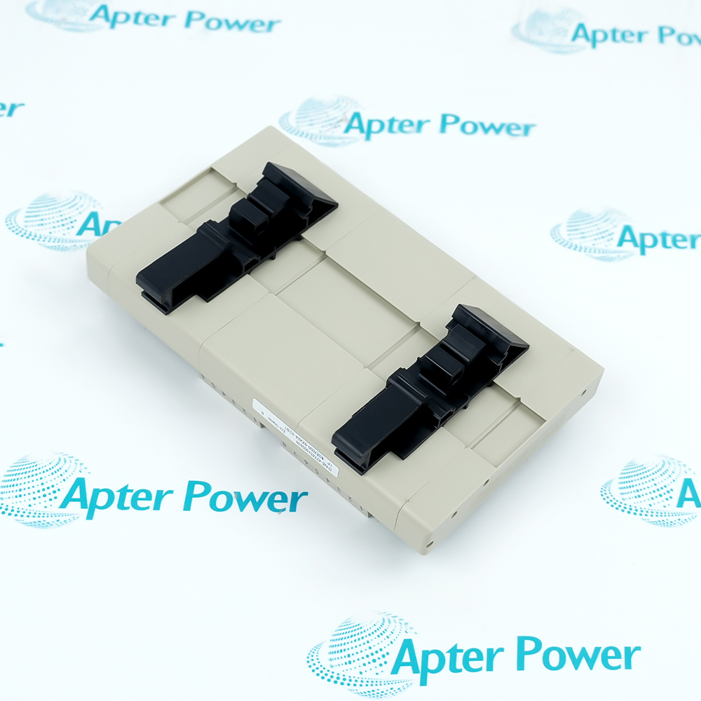
The DTI mounts on a rail and requires a separate isolated 24 Vdc supply; power and control cables are routed separately inside the cabinet. Start-up covers encoder type, TTL/HTL terminal selection, CU2/CUVC/CUVP or TSY connection, screen grounding and the applicable drive parameters.

Important Notice: Confirm 6SE7090-0XX84-3DB1 identity, MASTERDRIVES family and control board, rail and enclosure, TTL/HTL encoder type, X401/X402 selection, X403/X405 routing, 24 Vdc supply, X80/X81 screen grounding, cable length, drive parameters and controlled rotation test before commissioning.

Apter Power 6SE7090-0XX84-3DB1 Manuals and Guides

The first document is the model-specific technical and system reference. The second is a distinct field workbook for installation, wiring, commissioning and acceptance records.


SIMOVERT vector-control feedback
Conditions digital tachometer tracks for CU2, CUVC or CUVP speed-control applications.
SIMOVERT FC synchronization
Routes the DTI output through a TSY tachometer and synchronization board to the drive control.
TTL encoder integration
Receives complementary five-volt pulse tracks through the X401 terminal strip.
HTL encoder integration
Receives higher-level tachometer pulse tracks through X402 with the required external supply.
Read the applicable Siemens installation instructions before work. Verify 6SE7090-0XX84-3DB1, the installed host system and all configured field interfaces before isolation, wiring or commissioning.
1
Confirm the complete 6SE7090-0XX84-3DB1 marking and DB1 hardware.
2
De-energize the drive and verify the motor cannot turn before work.
3
Confirm the rail mounting and cabinet protection against direct contact.
4
Select only X401 for TTL or X402 for HTL input wiring.
5
Record X403/X405 control-board routing and every pulse-track conductor.
6
Use screened cable and bond screens at X80 and X81.
7
Verify the isolated 24 Vdc supply and encoder current requirement.
8
Set the applicable MASTERDRIVES encoder parameters and prove direction and speed feedback.

Technical notes

Technical notes

Snap 6SE7090-0XX84-3DB1 onto the mounting rail inside a protective cabinet, use screened cables and bond the screens at X80 and X81. Select only one input connector, X401 for TTL or X402 for HTL, then verify X403/X405 routing and the drive encoder parameters before rotation.

FAQS

  • What is the exact system role of 6SE7090-0XX84-3DB1?
    It is the SIMOVERT MASTERDRIVES DTI board that accepts isolated digital tachometer inputs and forwards conditioned pulse tracks.
  • Which host, rack or carrier is required for 6SE7090-0XX84-3DB1?
    Mount it on a rail inside the protected drive enclosure and connect it to CU2/CUVC/CUVP or a TSY path exactly as shown for the installed MASTERDRIVES system.
  • What wiring or connector checks apply to 6SE7090-0XX84-3DB1?
    Use X401 only for TTL or X402 only for HTL, route X403/X405 to the documented control hardware, and bond screens at X80/X81.
  • How is 6SE7090-0XX84-3DB1 configured for service?
    Select the tachometer type and set the applicable MASTERDRIVES encoder source, pulse-count and board-slot parameters.
  • Which diagnostics should be reviewed for 6SE7090-0XX84-3DB1?
    Review encoder track validity, tachometer direction and speed indication, drive diagnostics and the external 24 Vdc supply.
  • What must be preserved when replacing 6SE7090-0XX84-3DB1?
    Preserve terminal assignments, encoder type, pulse count, board slot, screen bonds, control-board route and existing parameter record.
  • How should 6SE7090-0XX84-3DB1 be commissioned after installation?
    Keep the drive de-energized until checks are complete, then run a controlled rotation test and compare indicated speed and direction.
  • What model-specific limitation must be checked for 6SE7090-0XX84-3DB1?
    DB1 replaces DB0 and provides an extended voltage range at X403.6; confirm the exact control-board and supply arrangement before substitution.
Trusted by 5,000+ plants worldwide | Backed by our vast inventory of top-tier control parts, modules and cards, fast shipments are dispatched to cover your urgent needs. ABOUT US >>
Disclaimer: We are not an authorized distributor or distributor of the product manufacturer of this website, The product may have older date codes or be an older series than that available direct from the factory or authorized dealers. Because our company is not an authorized distributor of this product, the Original Manufacturer`s warranty does not apply.While many DCS PLC products will have firmware already installed, Our company makes no representation as to whether a DSC PLC product will or will not have firmware and, if it does have firmware, whether the firmware is the revision level that you need for your application. Our company also makes no representations as to your ability or right to download or otherwise obtain firmware for the product from our company, its distributors, or any other source. Our company also makes no representations as to your right to install any such firmware on the product. Our company will not obtain or supply firmware on your behalf. It is your obligation to comply with the terms of any End-User License Agreement or similar document related to obtaining or installing firmware.

We’re Here When You Need Us

From product insights to customer service needs, our experienced service team will focus on getting you what you need quickly

Enquire

Complete our online form.

Call Us

Speak to one of our team.

Live Chat

Send us a message.
