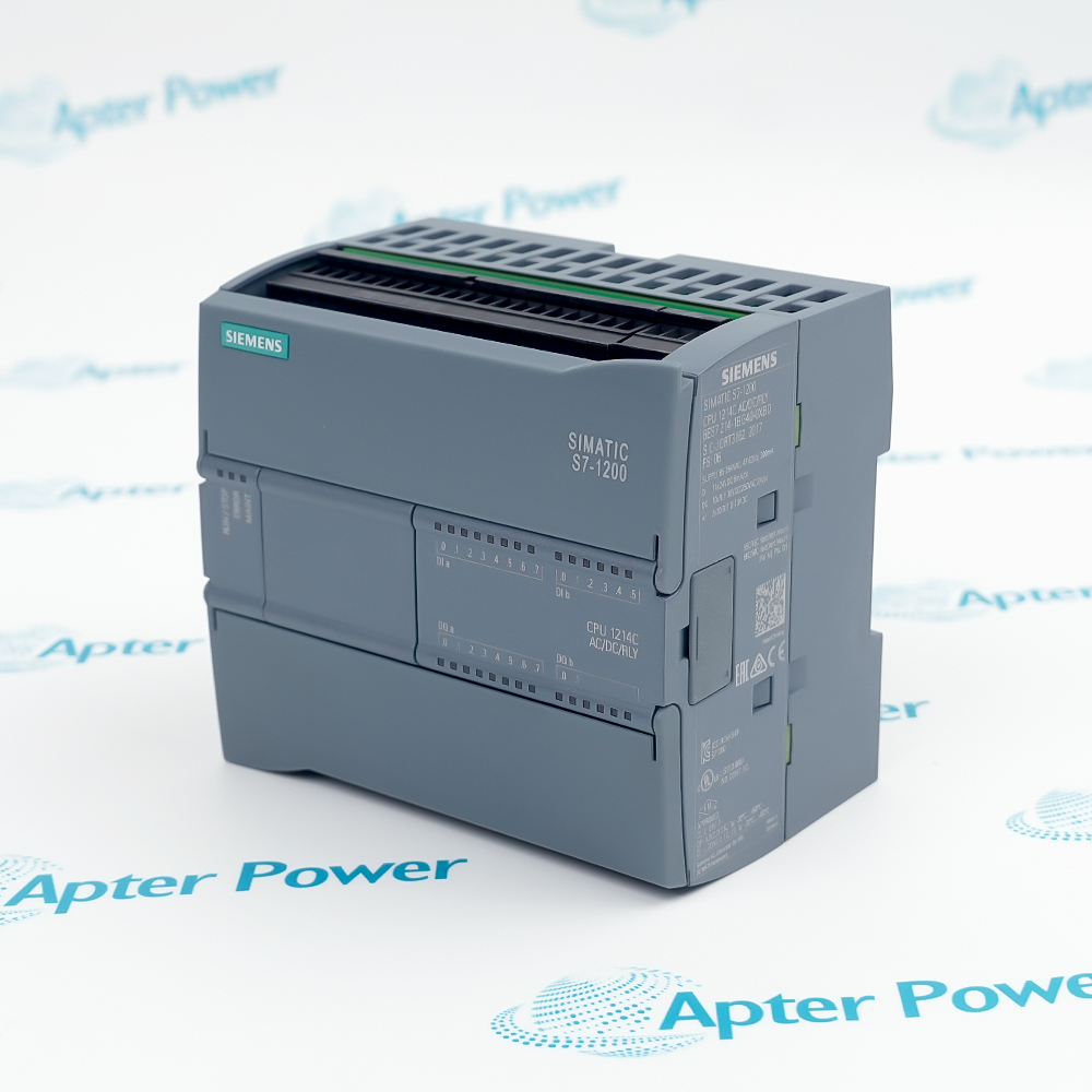
The Siemens 6ES7288-5AQ01-0AA0 is a SIMATIC S7-200 SMART SB AQ01 Analog Output Signal Board that provides one analog output channel for -10 V to +10 V or 0 to 20 mA.
- SB AQ01
- 1 analog output for voltage or current
- Powered by the compatible CPU and wired according to the Siemens signal-board instructions
- 35 x 52.2 x 16 mm
In an S7-200 SMART automation station, it converts one controller output value into a configured voltage or current command with onboard diagnostics. It works with the exact CPU, expansion-bus or signal-board interface, wiring, field devices, and project configuration specified for the complete article number. It is applied in single drive references, control valves, analog indicators, and compact actuator commands.
Important Notice: Use the complete 6ES7288-5AQ01-0AA0 code and verify the physical nameplate, current Siemens documentation, signal range, wiring, project, and accessories before installation or replacement.
Apter Power 6ES7288-5AQ01-0AA0 Manuals and Guides
Important Notice: These are two separate Apter Power documents prepared from the manufacturer-published Siemens information named in each document. Confirm the physical nameplate, current Siemens documents, and host-system requirements before installation or replacement.
Analog actuator command
Generates 1 analog output for voltage or current from PLC output values
Drive and valve reference
Provides configured voltage or current commands to compatible field devices
Setpoint transmission
Supports single drive references, control valves, analog indicators, and compact actuator commands with documented load and signal limits
Compact panel expansion
Adds analog command capability while preserving exact MLFB verification
Read the exact Siemens S7-200 SMART documentation before use. Verify 6ES7288-5AQ01-0AA0, SB AQ01, host system, signal type, wiring, and project from the physical installation.
1
Identity: Match every character of 6ES7288-5AQ01-0AA0 and the SB AQ01 marking to the physical nameplate and project
2
Host and power: Verify Powered by the compatible CPU and wired according to the Siemens signal-board instructions; isolate all energy sources before insertion, removal, or wiring
3
Signals: Configure every channel for the documented signal type and range; observe polarity, reference, load, and diagnostic limits
4
Cabling: Follow Siemens terminal, shielding, grounding, separation, and maximum cable-length instructions
5
Commissioning: Verify addresses and scaling, energize one circuit group at a time, test fail-safe behavior, and record results


 Videos
 News
News Applications