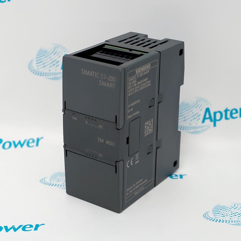
The Siemens 6ES7288-2QR16-0AA0 is a SIMATIC S7-200 SMART SM QR16 Relay Output Module that provides sixteen relay-only outputs in a 45 mm expansion module.
- SM QR16
- 16 relay digital outputs
- 24 V DC nominal; 20.4 to 28.8 V DC permissible
- 45 x 100 x 81 mm
In an S7-200 SMART automation station, it converts sixteen controller output bits into isolated dry-contact relay switching for approved AC or DC field loads. It works with the verified CPU or expansion-bus configuration, terminal blocks, field power, sensors, and actuators defined for the exact article number. The module is used in banked solenoids, contactor groups, alarms, lamps, and multi-actuator machine sections.
Important Notice: Use the complete 6ES7288-2QR16-0AA0 code and verify the physical nameplate, current Siemens documentation, field wiring, project, and accessories before installation or replacement.
Apter Power 6ES7288-2QR16-0AA0 Manuals and Guides
Important Notice: These are two separate Apter Power documents prepared from the manufacturer-published Siemens information named in each document. Confirm the physical nameplate, current Siemens documents, and host-system requirements before installation or replacement.
Isolated load switching
Commands 16 approved relay-controlled AC or DC circuits
Contactor and valve control
Interfaces controller logic with contactors, solenoids, lamps, and interposing relays
Mixed-voltage auxiliaries
Uses dry relay contacts where the published contact and group limits are respected
Machine and process panels
Supports banked solenoids, contactor groups, alarms, lamps, and multi-actuator machine sections
Read the exact Siemens S7-200 SMART documentation before use. Verify 6ES7288-2QR16-0AA0, SM QR16, power, I/O wiring, terminals, and project from the physical installation.
1
Identity: Match every character of 6ES7288-2QR16-0AA0 and the SM QR16 marking to the physical nameplate and project
2
Power: Verify 24 V DC nominal; 20.4 to 28.8 V DC permissible; isolate all energy sources before wiring, insertion, or removal
3
Signals: Observe every input/output voltage, current, common, group, polarity, isolation, and protective-device limit
4
Panel: Use documented DIN-rail mounting, clearances, protective earth, cable segregation, ventilation, and IP20 enclosure protection
5
Commissioning: Back up the project, verify addresses and terminals, test one circuit group at a time, and record the results


 Videos
 News
News Applications