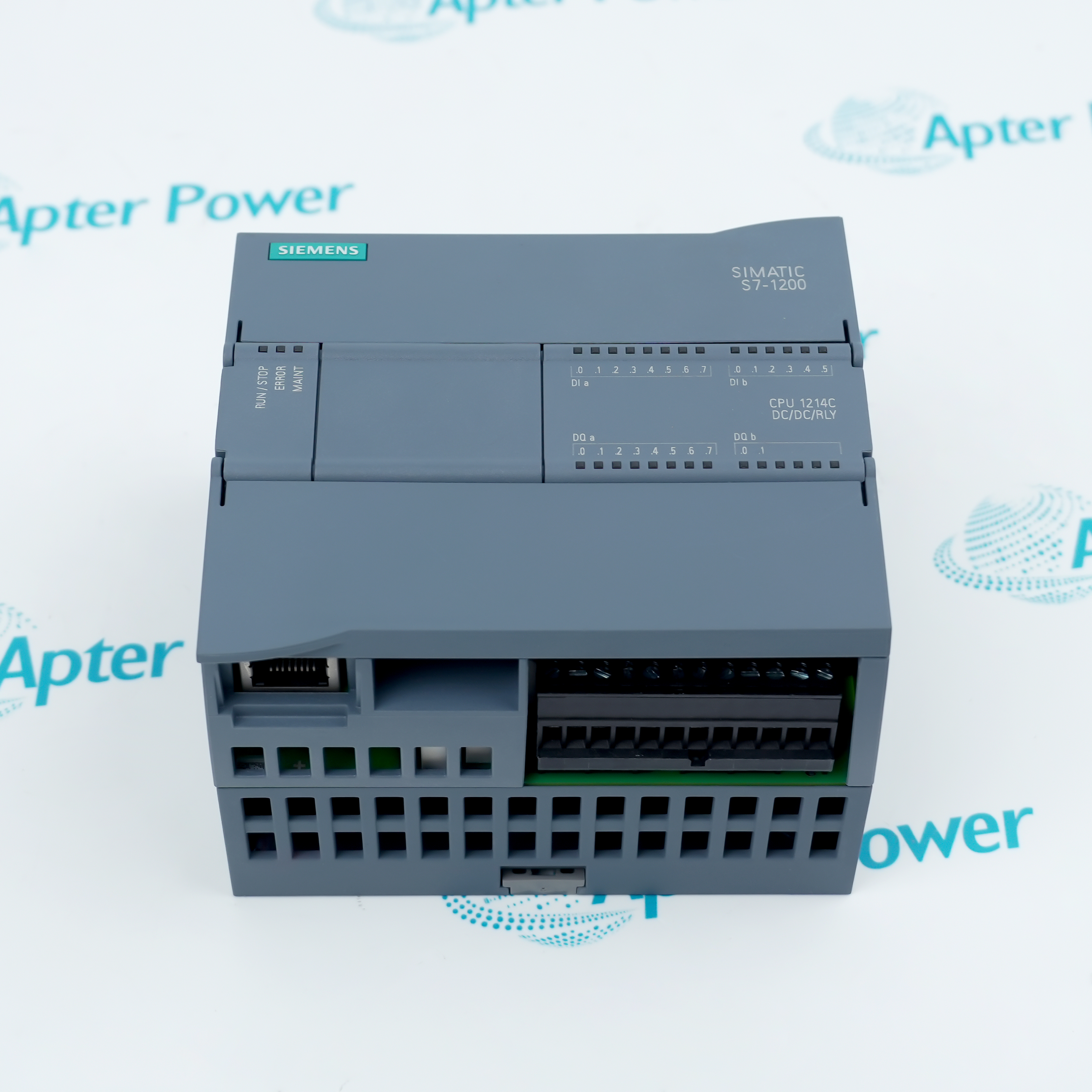
The Siemens 6ES7288-2DR16-0AA0 is a SIMATIC S7-200 SMART SM DR16 Digital I/O Module that provides balanced eight-input and eight-relay-output expansion.
- SM DR16
- 8 DI 24 V DC; 8 relay DQ
- 24 V DC nominal; 20.4 to 28.8 V DC permissible
- 45 x 100 x 81 mm
In an S7-200 SMART automation station, it acquires eight 24 V DC field states and returns eight isolated relay commands through one mixed digital I/O module. It works with the verified CPU or expansion-bus configuration, terminal blocks, field power, sensors, and actuators defined for the exact article number. The module is used in compact actuator stations, valve manifolds, indexed conveyors, and local machine cells.
Important Notice: Use the complete 6ES7288-2DR16-0AA0 code and verify the physical nameplate, current Siemens documentation, field wiring, project, and accessories before installation or replacement.
Apter Power 6ES7288-2DR16-0AA0 Manuals and Guides
Important Notice: These are two separate Apter Power documents prepared from the manufacturer-published Siemens information named in each document. Confirm the physical nameplate, current Siemens documents, and host-system requirements before installation or replacement.
Isolated load switching
Commands 8 approved relay-controlled AC or DC circuits
Contactor and valve control
Interfaces controller logic with contactors, solenoids, lamps, and interposing relays
Mixed-voltage auxiliaries
Uses dry relay contacts where the published contact and group limits are respected
Machine and process panels
Supports compact actuator stations, valve manifolds, indexed conveyors, and local machine cells
Read the exact Siemens S7-200 SMART documentation before use. Verify 6ES7288-2DR16-0AA0, SM DR16, power, I/O wiring, terminals, and project from the physical installation.
1
Identity: Match every character of 6ES7288-2DR16-0AA0 and the SM DR16 marking to the physical nameplate and project
2
Power: Verify 24 V DC nominal; 20.4 to 28.8 V DC permissible; isolate all energy sources before wiring, insertion, or removal
3
Signals: Observe every input/output voltage, current, common, group, polarity, isolation, and protective-device limit
4
Panel: Use documented DIN-rail mounting, clearances, protective earth, cable segregation, ventilation, and IP20 enclosure protection
5
Commissioning: Back up the project, verify addresses and terminals, test one circuit group at a time, and record the results


 Videos
 News
News Applications