











Get Parts Quote
Name
Company *
Phone *
Email *
Address
City
State / Province / Region
Zipcode
Country
Quantity *
Part Number *
Manufacturer
Preferred Condition
Additional Information
Cancel
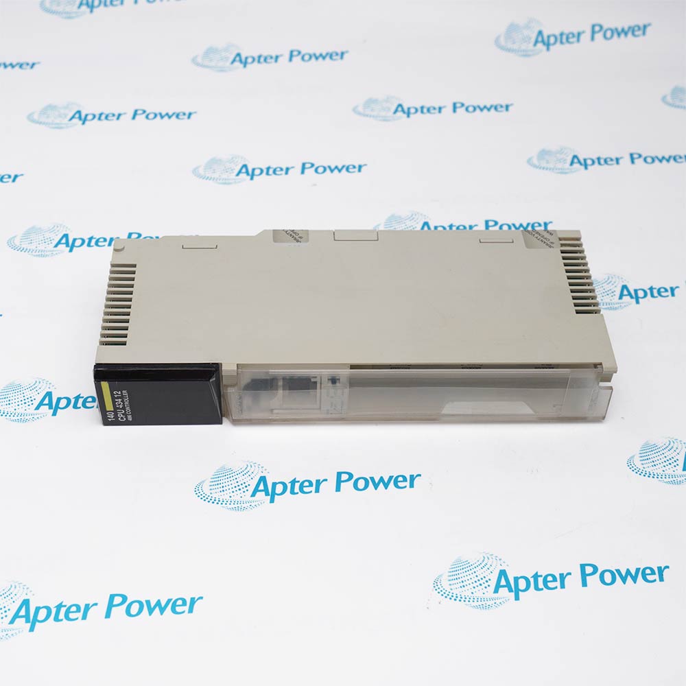
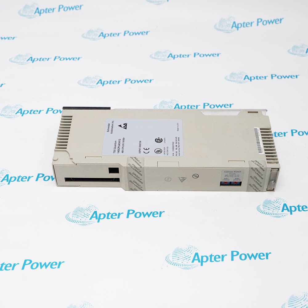
Schneider Electric 140CPU43412
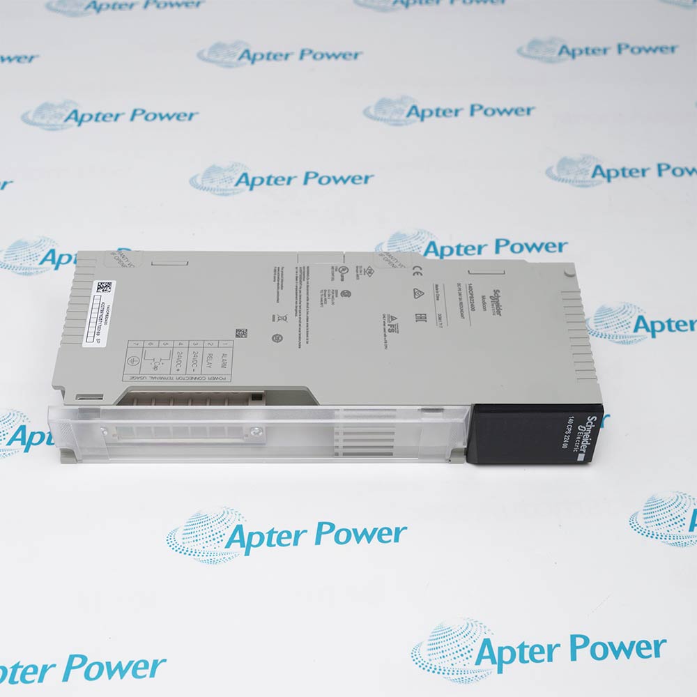
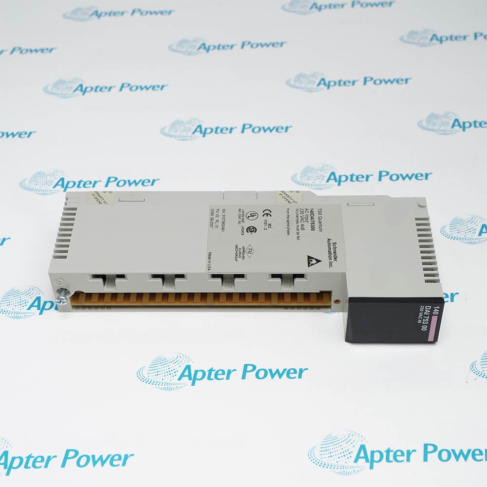
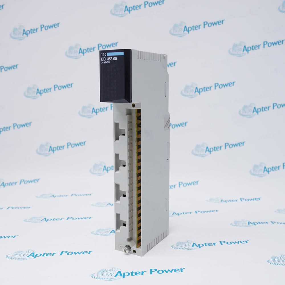
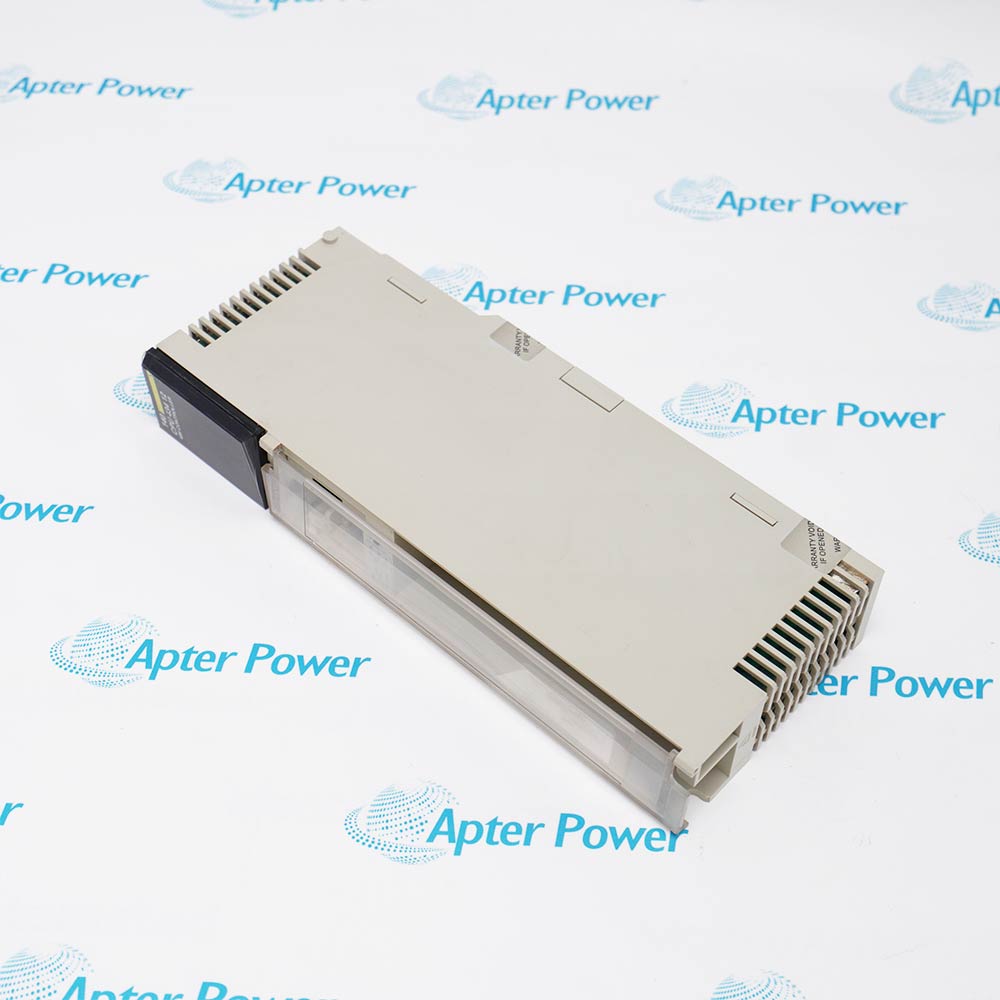
Product image is representative; revision or series may vary. Contact us to request a specific version.

140CPU43412

CPU Module
In Stock
Ships by Sunday, October 18
Fast Shipping Available

Product Describe:

Schneider Electric 140CPU43412 is a Modicon Quantum CPU with 2 MB SRAM, two RS-232 Modbus ports and one Modbus Plus network port. It executes the configured control application and coordinates local, remote and distributed I/O within the supported Quantum architecture.

Ask our team:

Get a quick price for: 140CPU43412
Quantity*
Upload (gif, jpg, jpeg, png, bmp, doc, docx, xls, xlsx, ppt, pdf, csv)
For more information on how your data is processed and stored by Apterpower please read our privacy policy.

Technical specifications for 140CPU43412

Technical specifications for 140CPU43412

  • Manufacturer:
    Schneider Electric
  • Product Category:
    PLC Systems
  • Spare Part Number:
    140CPU43412
  • Estimated shipping dimensions:
    4x10.5x25cm
  • Weight:
    0.58 kg
  • Tariff Code:
    8537101190
  • Counliy of origin:
    FRANCE
  • SRAM capacity:
    2 MB
  • Maximum IEC program:
    896 k
  • 984 ladder-logic capacity:
    64 k words
  • Discrete reference capacity:
    64 k, any mix
  • Register capacity:
    57 k
  • Extended register capacity:
    96 k
  • Modbus serial ports:
    2, RS-232, 9-pin D-shell
  • Modbus Plus ports:
    1, RS-485, 9-pin D-shell
  • Local I/O capacity:
    64 input words and 64 output words
  • Maximum local racks:
    2, requires expander
  • Maximum remote drops:
    31
  • Remote I/O capacity per drop:
    64 input words and 64 output words
  • Maximum DIO networks:
    3, requires two 140NOM21x00 modules
  • DIO capacity per network:
    500 input words and 500 output words
  • DIO capacity per node:
    30 input words and 32 output words
  • Option-module interfaces:
    Up to 6; only 2 Modbus Plus modules with full DIO functionality
  • Watchdog timer:
    250 ms, software-adjustable
  • Logic solve time:
    0.1-0.5 ms/k
  • Battery type:
    3 V lithium, 1200 mAh
  • Operating temperature:
    0-60 degrees C
  • TOD clock accuracy:
    +/-8 seconds/day at 0-60 degrees C
  • Fixed ASCII setting:
    2400 baud, even parity, 7 data bits, 1 stop bit
  • Fixed RTU setting:
    9600 baud, even parity, 8 data bits, 1 stop bit
  • Rear-switch node range:
    1-64
  • Software Modbus address range:
    1-247
  • Modem-capable serial interface:
    Modbus port 1; port 2 does not support modems

Information

Information

Overview Manuals Common Applications Product Precautions
Schneider Electric 140CPU43412 executes the Quantum control application and connects the CPU to its configured I/O and communication services. Its non-A hardware and executive identity must remain explicit during service or migration.
  • Coordinates the configured local and remote I/O image.
  • Supports distributed I/O through the documented Modbus Plus architecture.
  • Separates serial Modbus communication from the Modbus Plus network.
  • Provides front-panel diagnostics and memory-protection controls.

Use the recorded rack configuration, I/O map and communication settings as the integration baseline. After replacement, confirm the application, processor state and each configured communication path before releasing the process.

Important Notice: 140CPU43412 and 140CPU43412A require different flash executives; hot-standby pairs must use matching A or non-A CPU identities.

Schneider Electric 140CPU43412 Manuals & Downloads
Schneider Electric 140CPU43412 Technical Reference (PDF)Schneider Electric 140CPU43412 Installation & Commissioning Guide (PDF)

The technical reference separates CPU resources, interfaces and diagnostic states; the installation guide covers switch setup, application restoration, communication checks and controlled start-up.


Quantum control executionRuns the installed control logic and coordinates the configured local I/O image.
Remote-drop coordinationSupports the documented Quantum remote-I/O architecture through the configured RIO head interface.
Modbus-connected equipmentExchanges serial data using the selected ASCII, RTU or software-defined communication settings.
Distributed I/O integrationUses the Modbus Plus architecture and the required option modules for the configured DIO networks.
Read the Quantum hardware instructions before work. Verify 140CPU43412, the non-A executive, rack configuration, communication switches and the approved process maintenance state.
1
Keep the exact non-A CPU identity; do not load a 140CPU43412A flash executive.
2
For hot standby, use two matching non-A CPUs or two matching A CPUs, never one of each.
3
Set the key switch and memory-protection controls for the authorized maintenance operation.
4
Retain the rear rotary-switch address within 1-64; zero or values above 64 are invalid for Modbus Plus.
5
Match the front communication switch to the actual serial client; fixed ASCII and RTU modes use different baud and data-bit settings.
6
Connect modem equipment to Modbus port 1; port 2 does not provide full modem support.
7
Respect I/O-word allocations and the required expander or option modules; do not infer capacity from the connector count.
8
Confirm Ready, Run, memory protection and communication indications before returning the restored controller to service.

Technical notes

Technical notes

Keep the non-A executive and hot-standby identity separate from 140CPU43412A. Match the communication switch positions and rear node address to the restored application before starting the controller.

FAQS

  • Can 140CPU43412 use the same flash executive as 140CPU43412A?
    No. The A and non-A executives are not interchangeable. In hot standby, pair two non-A CPUs or two A CPUs rather than mixing them.
  • Which 140CPU43412 Modbus port can be connected to a modem?
    Port 1 provides full modem interfacing. Port 2 supports normal RTS/CTS serial communication but not modem operation.
  • Why does the 140CPU43412 Modbus Plus indicator stay on after changing the rear switches?
    An address of zero or a value above 64 is invalid and produces a steady Modbus Plus indication. The upper switch sets tens and the lower switch sets units; use a valid unique node from 1 to 64.
  • What changes when the 140CPU43412 communication selector moves between ASCII and RTU?
    The fixed ASCII position uses 2400 baud, even parity, seven data bits and one stop bit. Fixed RTU uses 9600 baud, even parity, eight data bits and one stop bit. The bottom position permits software-defined settings.
  • Does the 140CPU43412 Mem Prt key position stop a running controller?
    It prevents programmer changes without changing the current run state. The Stop position stops the controller; the Start position permits programmer changes and programmer start/stop commands.
  • What expansion is required for a second local rack on 140CPU43412?
    The supported two-rack local configuration requires an expander. Local I/O allocation remains limited to 64 input words and 64 output words, with discrete and register I/O consuming that allocation.
  • How should 140CPU43412 distributed-I/O capacity be checked?
    Three DIO networks require two 140NOM21x00 option modules. Each network allows 500 input and 500 output words; each node allows 30 input and 32 output words, and drop overhead must be included.
  • Which diagnostic indications distinguish start-up from execution on 140CPU43412?
    Ready means power-up diagnostics have passed; Run means logic is being solved. Bat Low identifies a missing or depleted battery, while Error A identifies a Modbus Plus communication error.
Trusted by 5,000+ plants worldwide | Backed by our vast inventory of top-tier control parts, modules and cards, fast shipments are dispatched to cover your urgent needs. ABOUT US >>
Disclaimer: We are not an authorized distributor or distributor of the product manufacturer of this website, The product may have older date codes or be an older series than that available direct from the factory or authorized dealers. Because our company is not an authorized distributor of this product, the Original Manufacturer`s warranty does not apply.While many DCS PLC products will have firmware already installed, Our company makes no representation as to whether a DSC PLC product will or will not have firmware and, if it does have firmware, whether the firmware is the revision level that you need for your application. Our company also makes no representations as to your ability or right to download or otherwise obtain firmware for the product from our company, its distributors, or any other source. Our company also makes no representations as to your right to install any such firmware on the product. Our company will not obtain or supply firmware on your behalf. It is your obligation to comply with the terms of any End-User License Agreement or similar document related to obtaining or installing firmware.

Product Browsing History

We’re Here When You Need Us

From product insights to customer service needs, our experienced service team will focus on getting you what you need quickly

Enquire

Complete our online form.

Call Us

Speak to one of our team.

Live Chat

Send us a message.
