
-
Manufacturers
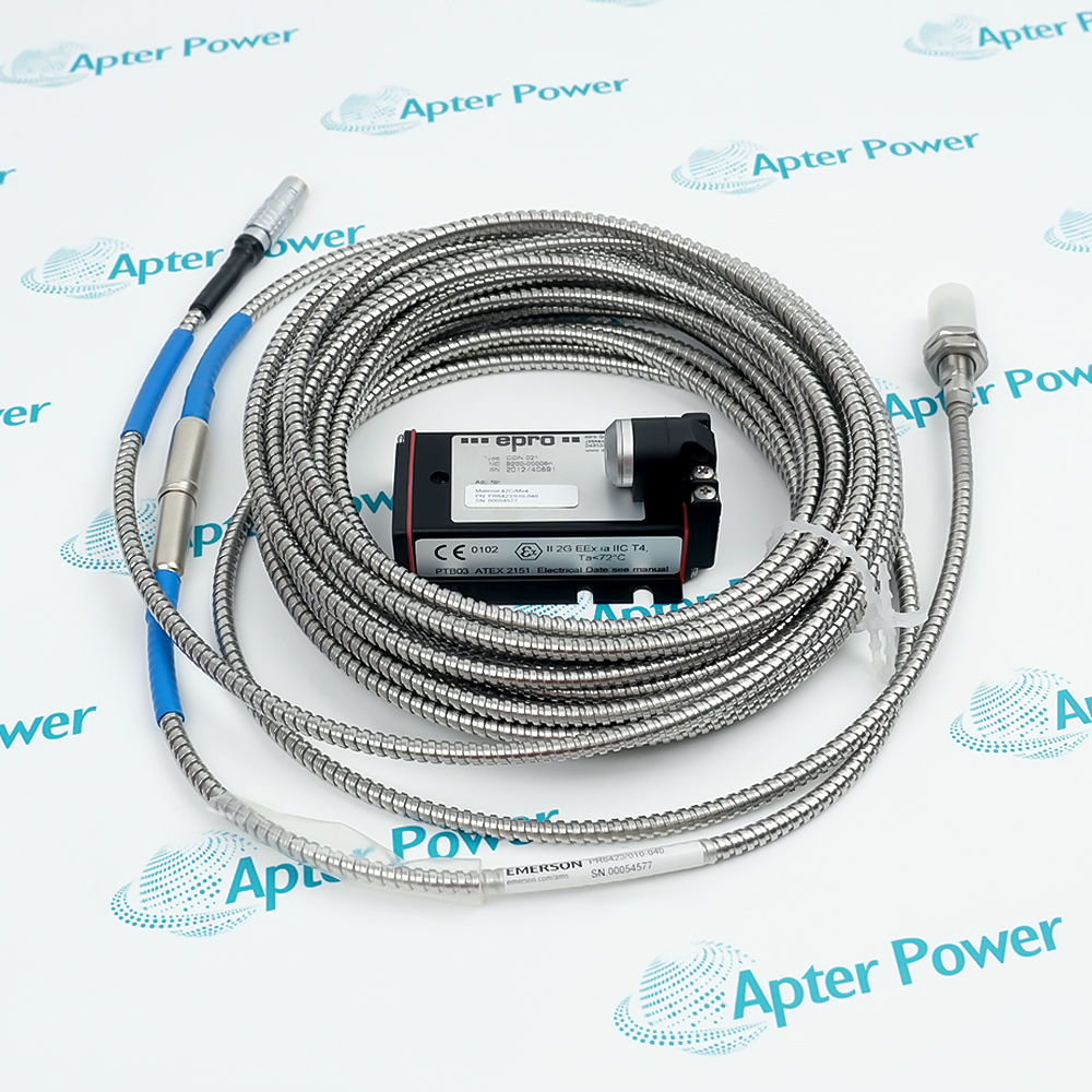
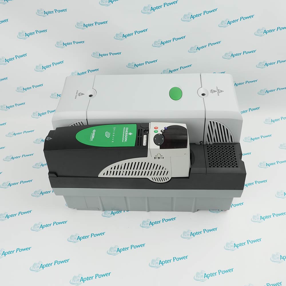
With more than 30.000 high-quality spare parts, they can be sold immediately. Our large inventory allows us to quickly meet customer needs, thereby reducing downtime and protecting production schedules. Our timely delivery time provides you with security and save money.
-
-
Resources
-
 Videos
-
 News
-
 Applications
-
-
Please try to be as accurate as possible with your search.
-
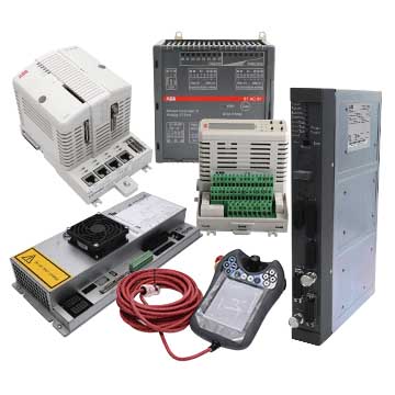
We can quote you on 1000s of specialist parts, even if they are not listed on our website.
-
We can't find any results for “”.
SEE PRODUCTS IN SEARCH PAGE ()
Get Parts Quote