

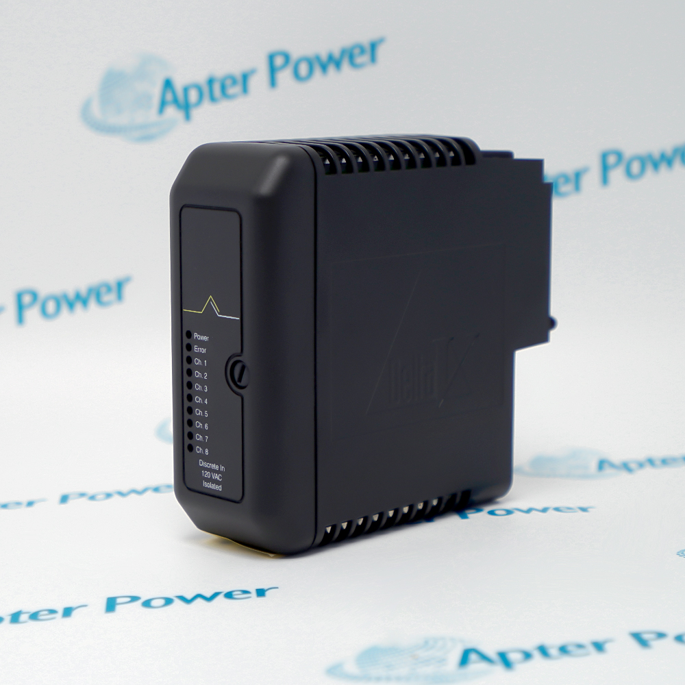
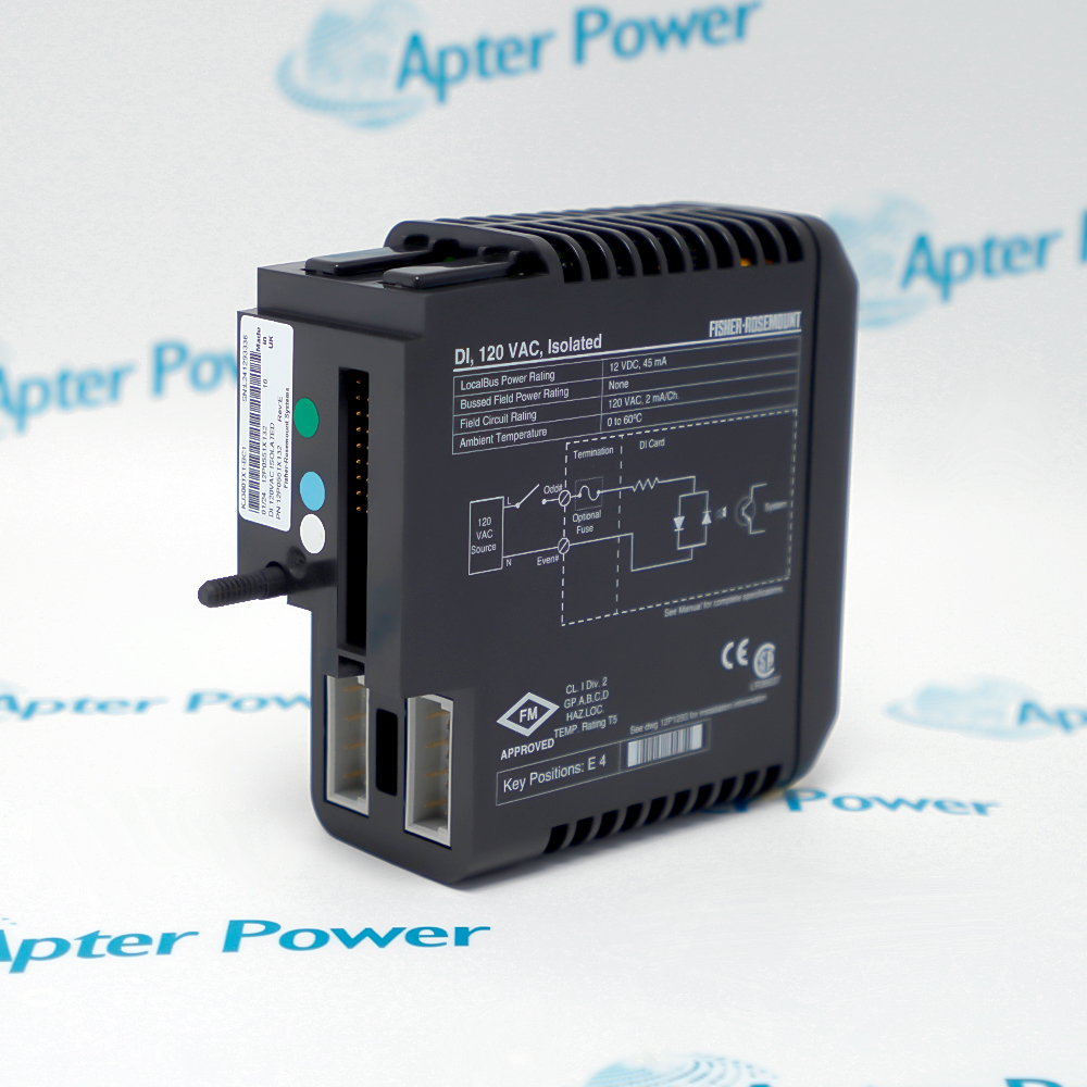
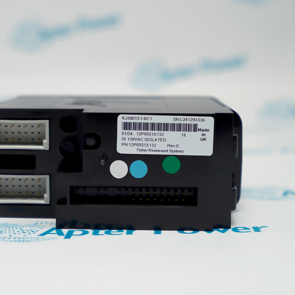











Use Emerson KJ3001X1-BC1-12P0551X132-VE4001S3T1B1 only after matching the complete installed nameplate, the VE4001S3T1B1 termination-block identity, the 120 V AC isolated-input function and the documented DeltaV carrier arrangement. The current Emerson PDS verifies VE4001S3T1B1; it does not decode the older KJ3001X1-BC1 or 12P0551X132 portions.
The official Emerson ordering table verifies VE4001S3T1B1 as the standard termination block for the eight-channel 120 V AC isolated discrete-input function.
Important Notice: Confirm the complete KJ3001X1-BC1-12P0551X132-VE4001S3T1B1 marking before work. Isolate the controller and all 120 V AC field circuits, preserve terminal assignments and keying, and test every channel under a controlled maintenance procedure before return to service.
These documents are different: the first consolidates exact product and system data; the second provides model-specific installation checks, commissioning steps and acceptance guidance.
Acquire eight independently isolated AC discrete states in a DeltaV M-series Traditional I/O subsystem.
Monitor documented 120 V AC permissive, limit or interlock contacts through the isolated input channels.
Use the standard I/O termination block on the documented DeltaV carrier while preserving field terminal assignments.
Restore the complete KJ3001X1-BC1-12P0551X132-VE4001S3T1B1 identity without normalizing legacy nameplate portions.
Verify the complete KJ3001X1-BC1-12P0551X132-VE4001S3T1B1 nameplate before work.
Place the DeltaV controller and all associated 120 V AC field circuits in the approved maintenance state.
Confirm that VE4001S3T1B1 is the required standard termination block for the installed eight-channel isolated-input function.
Record all eight field-wire assignments, channel labels and the existing function-key arrangement before removal.
Do not substitute interpretations for the legacy KJ3001X1-BC1 or 12P0551X132 markings; retain them as installed identity.
Install the card and terminal block only in the correctly keyed DeltaV M-series carrier position.
Provide an enclosure appropriate for the IP20 equipment and keep operation within the documented environmental limits.
After energization, verify power and error indications and function-test all eight channels before service release.



Copyright Notice © 2026 apterpower.com All rights reserved,Apter Power is not an authorised distributor or representative of the manufacturers featured on this website. Brand names and trademarks featured are the property of their respective owners.