The 84508-30 is a Bently Nevada 30 ft (approximately 9.0 m) high-temperature interconnection cable. The 84508 family uses two-wire shielded 22 AWG (0.5 mm2) cable with terminal lugs at both ends; the -30 suffix selects a 30 ft ordered length.
- 30 ft (approximately 9.0 m)
- Two-wire
- 22 AWG (0.5 mm2)
- Shielded
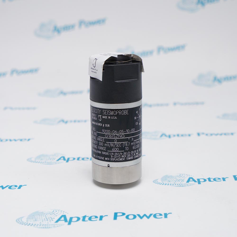
It carries the self-generated velocity signal from a 9200 or 74712 Seismoprobe installation through high-temperature field routing to terminal points, a monitor, or an intermediate junction. The shield controls electrical noise while the two conductors preserve the sensor's differential signal and polarity. For dependable operation, follow the official system-matching, mounting, wiring, environmental, and approval instructions.
Important Notice: Verify the 30 ft route, lug interfaces, two-wire polarity, shield termination, mechanical protection, temperature exposure, and end-to-end monitor response.
Apter Power 84508-30 Manuals and Guides
Important Notice: These are two separate Apter Power documents prepared from the official Bently Nevada source named in each document. Confirm the physical nameplate, current manufacturer documentation, and applicable installation drawing before installation or replacement.
74712 Seismoprobe Wiring
Routes a high-temperature velocity signal from the sensor to a monitor or junction.
9200 Seismoprobe Installations
Supports compatible two-wire terminal-lug connections where the cable specification is appropriate.
Turbine Bearing Housings
Carries casing-vibration signals away from hot machine surfaces.
Compressor and Pump Monitoring
Provides fixed shielded wiring for velocity measurement channels.
Field Junction Boxes
Terminates directly on screw or stud terminals through fitted lugs.
Protected Conduit Runs
Supports mechanically protected routing in industrial installations.
Read and follow the official manufacturer source and applicable installation instructions before use. Verify the exact complete ordering code from the physical nameplate.
1
Confirm that 30 ft is the required route length before installation; avoid hidden coils that add heat exposure or noise pickup.
2
Verify both terminal-lug sizes, conductor polarity, shield termination, and monitor input wiring against the current diagram.
3
Protect the unarmored cable in suitable conduit or mechanical protection and support it away from sharp edges and hot surfaces beyond its rating.
4
Do not substitute 84508 for an armored 84509 or connector-ended 84660/84510 cable without checking the complete interface.
5
Perform continuity, insulation, shield, and end-to-end signal checks before returning the monitoring channel to service.


 Videos
 News
News Applications