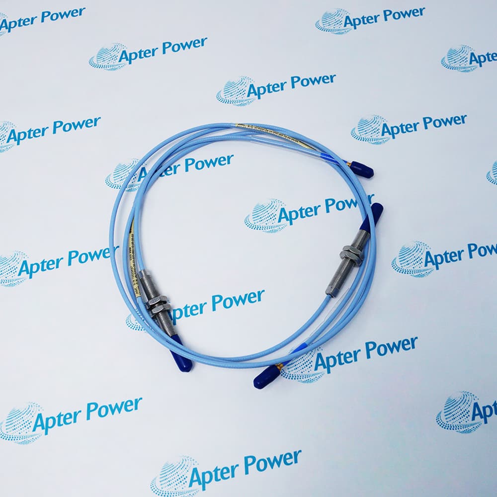
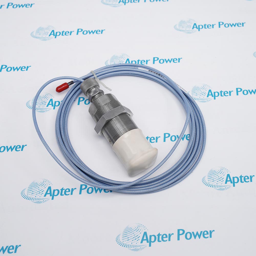
The 330101-39-47-10-02-05 is a Bently Nevada 3300 XL 8 mm unarmored proximity probe with 3/8-24 UNF threads, 3.9 in unthreaded length, 4.7 in case length, 1.0 m standard cable, ClickLoc connector without protector, and the CSA, ATEX, and IECEx approvals option.
- 3300 XL 8 mm unarmored proximity probe
- 3/8-24 UNF
- None
- 3.9 in
It senses distance to a conductive shaft or target and, with a correctly matched extension cable and Proximitor Sensor, supplies static-position and dynamic-vibration signals for machinery protection and condition monitoring. For dependable measurement, follow the official system-matching, target, mounting, cabling, environmental, and approval instructions.
Important Notice: The long 3.9 in unthreaded section is only 0.8 in shorter than the 4.7 in case, matching the ordering-table limit. Verify mounting clearance and certification.
Apter Power 330101-39-47-10-02-05 Original Product Manual
Important Notice: This Apter Power original manual summarizes manufacturer-published technical data for the exact ordering code. Verify the physical nameplate and current manufacturer installation documents before use.
Fluid-Film-Bearing MachineryProvides non-contacting shaft vibration and position measurements on rotating machinery equipped with fluid-film bearings.
Radial Shaft VibrationMeasures dynamic shaft motion relative to the long-case 3/8-24 UNF probe mounting location.
Static Shaft PositionMeasures the static gap between the probe tip and a conductive shaft or target through the complete transducer system output.
Keyphasor ReferenceSupports phase-reference measurement when the target geometry, Proximitor Sensor, and monitoring input meet official requirements.
Speed MeasurementSupports rotational-speed measurement when system length, target geometry, and monitoring-channel requirements are satisfied.
Machinery ProtectionSupplies a conditioned vibration or position signal to a compatible Bently Nevada monitoring system.
Read and follow Bently Nevada 3300 XL 8 mm Proximity Transducer System Datasheet 141194 Rev. AM and the applicable installation instructions before use. Verify the complete ordering code from the physical nameplate and match every component to the published system configuration.
1Keep the 3.9 in unthreaded length and 4.7 in case geometry clear of side-view and rear-view interference.
2Match the 1.0 m probe with either 4.0 m or 8.0 m of compatible extension cable for the selected 5 m or 9 m Proximitor Sensor.
3Maintain the 25.4 mm minimum bend radius and protect the unarmored lead from mechanical damage.
4Set the operating gap using the complete matched system and target material.
5Verify the 05 approval marking, barriers, and applicable hazardous-area drawing before installation.


 Videos
 News
News Applications