











Get Parts Quote
Name
Company *
Phone *
Email *
Address
City
State / Province / Region
Zipcode
Country
Quantity *
Part Number *
Manufacturer
Preferred Condition
Additional Information
Cancel
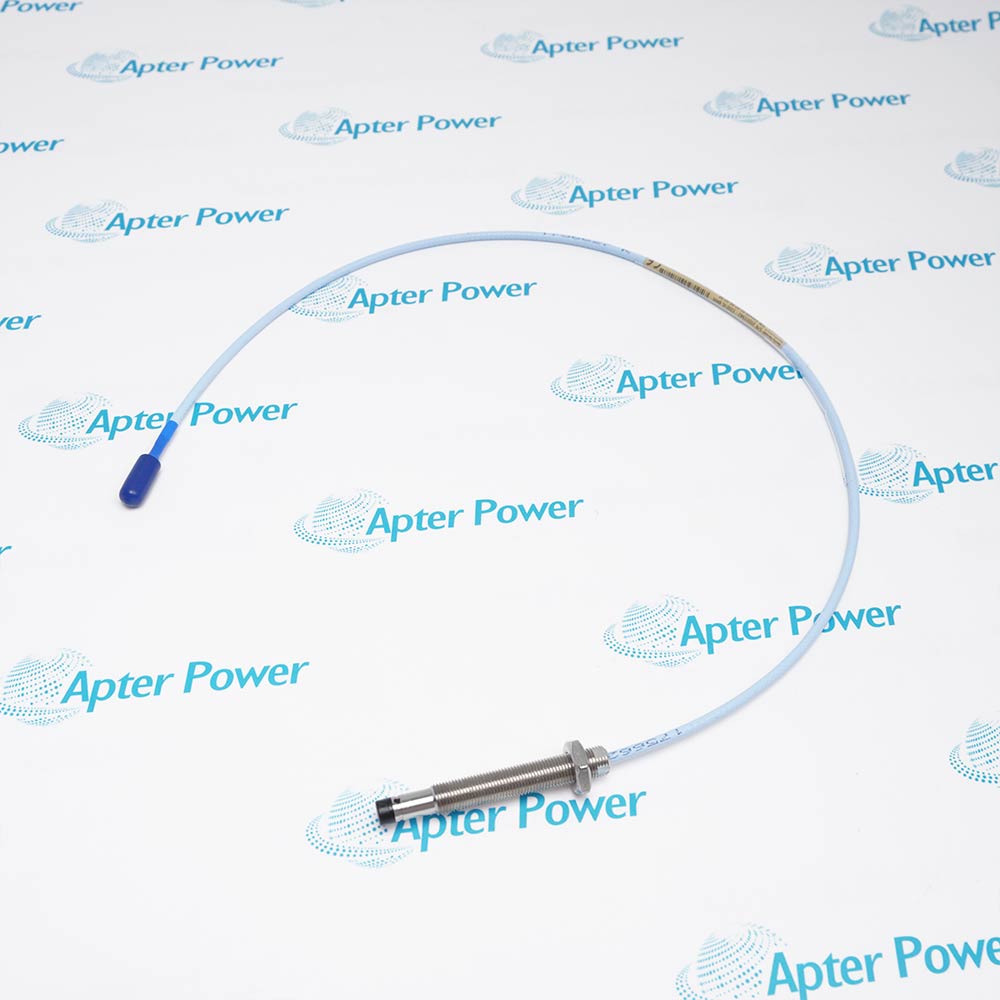
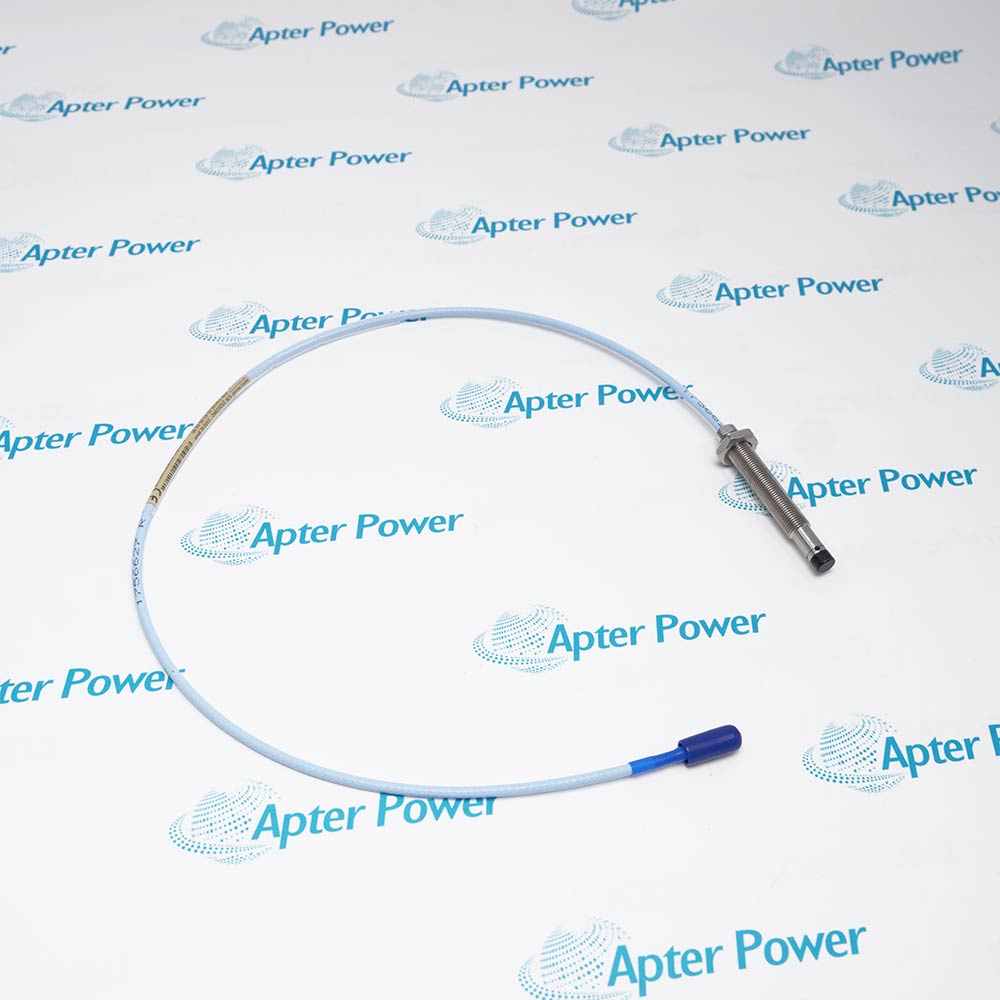
Bently Nevada 330103-01-07-05-02-00
Product image is representative; revision or series may vary. Contact us to request a specific version.

330103-01-07-05-02-00

Proximity Probe
In Stock
Ships by Wednesday, October 14
Fast Shipping Available

Product Describe:

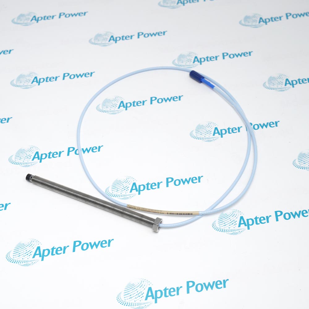
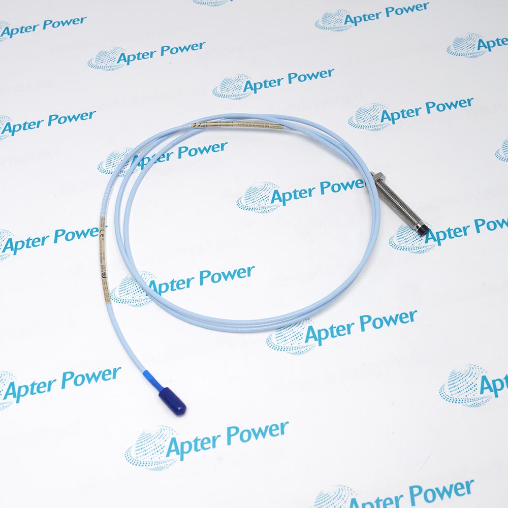
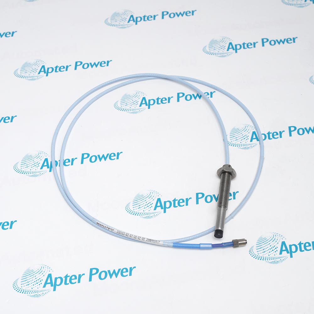
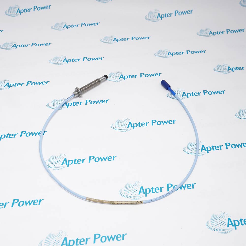
Bently Nevada 330103-01-07-05-02-00 is an unarmored M10 x 1 proximity probe with a 0.5 m standard lead. It measures shaft-relative vibration and position through a matched 3300 XL 8 mm transducer system.

Ask our team:

Get a quick price for: 330103-01-07-05-02-00
Quantity*
Upload (gif, jpg, jpeg, png, bmp, doc, docx, xls, xlsx, ppt, pdf, csv)
For more information on how your data is processed and stored by Apterpower please read our privacy policy.

Technical specifications for 330103-01-07-05-02-00

Technical specifications for 330103-01-07-05-02-00

  • Manufacturer:
    Bently Nevada
  • Product Category:
    Machinery Monitoring System
  • Spare Part Number:
    330103-01-07-05-02-00
  • Estimated shipping dimensions:
    1.8x1.6x117cm
  • Weight:
    0.1 kg
  • Tariff Code:
    8537101190
  • Counliy of origin:
    USA
  • Probe Family:
    3300 XL 8 mm
  • Mounting Thread:
    M10 x 1
  • Construction:
    Standard mount; without armor
  • Unthreaded Length:
    01 = 10 mm
  • Overall Case Length:
    07 = 70 mm
  • Total Probe Length:
    05 = 0.5 m
  • Connector:
    02 = miniature coaxial ClickLoc; no protector
  • Cable Type:
    Standard; 75 ohm triaxial; FEP insulation
  • Agency Approval Option:
    00 = not required
  • Probe Tip Material:
    Polyphenylene sulfide (PPS)
  • Probe Case Material:
    AISI 303 or 304 stainless steel
  • Connector Material:
    Gold-plated brass or beryllium copper
  • Nominal Probe DC Resistance:
    7.45 +/- 0.50 ohm
  • Maximum Connector Torque:
    0.565 N m
  • Standard Mount Recommended Case Torque:
    11.2 N m
  • Probe Operating / Storage Temperature:
    -52 to +177 deg C
  • Matched System Linear Range:
    2 mm; approximately 0.25 to 2.3 mm
  • Matched System Scale Factor:
    7.87 V/mm (200 mV/mil) nominal
  • Radial Vibration Gap Setting:
    -9 VDC nominal
  • Matched System Frequency Response:
    0 to 10 kHz; +0 / -3 dB
  • Calibration Target:
    AISI 4140 steel
  • Supported Electrical System Lengths:
    5 m with 4.5 m extension; 9 m with 8.5 m extension
  • Proximitor Maximum Current:
    12 mA
  • Proximitor Supply, Non-incendive Circuit:
    -17.5 to -26 VDC; per drawing 140979
  • Proximitor Supply with Barriers:
    -23 to -26 VDC
  • Proximitor Output Resistance:
    50 ohm
  • Proximitor Housing Material:
    A308 aluminum

Information

Information

Overview Manuals Common Applications Product Precautions
Bently Nevada 330103-01-07-05-02-00 is an unarmored M10 x 1 proximity probe with a 0.5 m standard lead. It measures shaft-relative vibration and position through a matched 3300 XL 8 mm transducer system.
  • Provides a short 0.5 m lead for an extension-based measurement chain.
  • Uses an M10 x 1 forward-mount interface without armor.
  • Carries a standard miniature coaxial ClickLoc service connection.
  • Supports static target position and dynamic shaft-motion signals.

The shorter probe lead changes the required extension arrangement. Select the correct 4.5 m or 8.5 m extension and matching conditioner, then verify the monitor input and target calibration as one channel.

Important Notice: This execution does not include the -01 connector protector or an agency-approved -05 selection. Provide suitable connection protection and independent process containment for the actual installation.

Bently Nevada 330103-01-07-05-02-00 Manuals & Downloads
330103-01-07-05-02-00 Technical Reference (PDF)330103-01-07-05-02-00 Installation & Commissioning Guide (PDF)

The technical reference covers configuration, signal characteristics and performance conditions. The installation guide organizes system pairing, connection checks and channel commissioning.


Short-lead bearing installations
Route the 0.5 m probe lead to its selected extension while supporting the unarmored cable at the receiving assembly.
Journal vibration channels
Measure shaft motion relative to a fluid-film bearing using the matched 5 m or 9 m 3300 XL sensing chain.
Static position channels
Use the DC gap component for an appropriate conductive target inside the calibrated operating region.
Machine reference signals
Acquire speed or phase-reference target movement when the target and monitor channel are configured for that purpose.
Bently Nevada 330103-01-07-05-02-00 installation checks: pair the 0.5 m lead with the specified extension, secure the connector junction and verify DC shaft-position response.
1
Use the selected 4.5 m or 8.5 m extension; the 0.5 m probe is not the direct 1 m sensor configuration.
2
Keep the M10 x 1 mounting interface and thread engagement consistent with the receiving assembly.
3
Arrange protection for the -02 junction and electrically insulate its coaxial connection from ground.
4
Use the reduced case-torque instruction where only the first three threads engage.
5
Connect only to the matched Proximitor sensing circuit; do not apply 220 VAC to the probe lead.
6
Verify the target calibration and -9 VDC radial-gap operating point before interpreting vibration.
7
Separate the broad temperature rating from calibration accuracy and pressure-seal behavior.
8
Support the lead without making the rated tensile strength a continuous operating load.

Technical notes

Technical notes

The 0.5 m probe requires the correct extension for a 5 m or 9 m transducer system. Option -02 supplies the standard ClickLoc connection without a protector; it is a sensing element, not a 220 VAC instrument.

FAQS

  • Which extension lengths complete a system using 330103-01-07-05-02-00?
    The 0.5 m probe uses a 4.5 m extension for a 5 m system or an 8.5 m extension for a 9 m system. Select the corresponding Proximitor electrical-length execution.
  • Is 220 VAC a valid operating supply for 330103-01-07-05-02-00?
    No. The probe connects to the matched Proximitor sensing circuit. The conditioning stage uses a negative DC supply: -17.5 to -26 VDC for the documented non-incendive circuit, or -23 to -26 VDC with barriers.
  • Does the 2 mm linear span associated with 330103-01-07-05-02-00 mean a bipolar plus/minus 1 mm output?
    The system provides a 2 mm target-distance span, approximately 0.25 to 2.3 mm, with about -1 to -17 VDC output. Position and voltage are interpreted from the installed operating point.
  • Can 330103-01-07-05-02-00 measure static position below 10 Hz?
    The matched-system response extends from DC to 10 kHz. The DC component represents static target position; 10 Hz is not the lower cutoff listed for this system.
  • What changes when only the first three case threads of 330103-01-07-05-02-00 engage?
    Use the reduced support-condition torque: 7.5 N m recommended and 22.6 N m maximum. Full standard forward-mount engagement has a different case-torque instruction.
  • Can the tensile-strength ratings of 330103-01-07-05-02-00 be used as installation pull targets?
    They are maximum component ratings, not recommended pulling forces: 330 N from case to lead and 270 N at the probe-lead-to-extension junction. Support the installed cable to avoid persistent strain.
  • Why can a less-negative sensor supply change the usable range with 330103-01-07-05-02-00?
    The conditioning-stage supply can reduce the usable linear range when it is more positive than -23.5 VDC. Check the voltage under the installed load and the applicable circuit requirements.
  • What target material establishes the standard calibration used with 330103-01-07-05-02-00?
    AISI 4140 steel is the standard target basis. Confirm the actual shaft material and applicable calibration before transferring the nominal scale factor to a different target.
Trusted by 5,000+ plants worldwide | Backed by our vast inventory of top-tier control parts, modules and cards, fast shipments are dispatched to cover your urgent needs. ABOUT US >>
Disclaimer: We are not an authorized distributor or distributor of the product manufacturer of this website, The product may have older date codes or be an older series than that available direct from the factory or authorized dealers. Because our company is not an authorized distributor of this product, the Original Manufacturer`s warranty does not apply.While many DCS PLC products will have firmware already installed, Our company makes no representation as to whether a DSC PLC product will or will not have firmware and, if it does have firmware, whether the firmware is the revision level that you need for your application. Our company also makes no representations as to your ability or right to download or otherwise obtain firmware for the product from our company, its distributors, or any other source. Our company also makes no representations as to your right to install any such firmware on the product. Our company will not obtain or supply firmware on your behalf. It is your obligation to comply with the terms of any End-User License Agreement or similar document related to obtaining or installing firmware.

We’re Here When You Need Us

From product insights to customer service needs, our experienced service team will focus on getting you what you need quickly

Enquire

Complete our online form.

Call Us

Speak to one of our team.

Live Chat

Send us a message.
