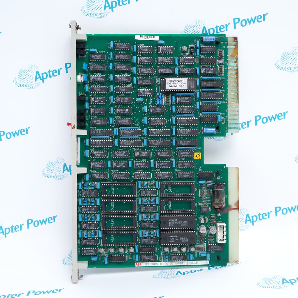
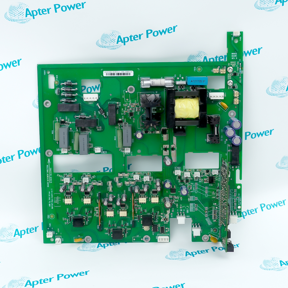
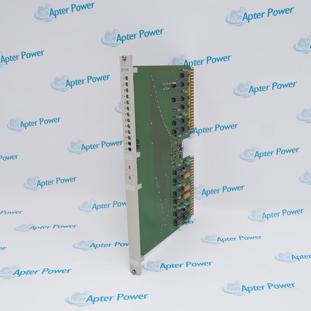
The Elsag Bailey IMSPM01 is a microprocessor-based INFI 90 Serial Port Module. It provides a serial communications path between a computer and INFI 90 modules installed in a Process Control Unit over the module bus.
- Serial Port Module
- 8-bit, 2 MHz
- 24 KB UVROM; 4 KB SRAM
- 2 full-duplex RS-232C ports
The IMSPM01 accepts Bailey and EWS commands for module tuning, configuration, status reporting and data transfer. It can communicate with up to 31 modules. One faceplate port supports a direct computer or modem connection; an optional termination unit exposes the second serial channel and a diagnostic-terminal path.
Important Notice: Keep the complete IMSPM01 marking unchanged and verify the physical nameplate, revision, companion hardware, and current ABB/Elsag Bailey documentation before installation or replacement.
Apter Power IMSPM01 Manuals and Guides
Important Notice: These are two separate Apter Power documents prepared from the official ABB/Elsag Bailey source named in each document. Confirm the physical nameplate, current manufacturer documentation, and applicable installation or system drawing before installation or replacement.
Control System Integration
Commissioning, supervisory data access, module configuration and diagnostics for INFI 90 process-control systems.
Signal and Data Handling
Two full-duplex RS-232C serial channels; it exchanges module configuration, status and process data rather than directly measuring field signals.
Companion Hardware
INFI 90 Process Control Unit, module bus, optional termination unit, computer or modem, compatible engineering/workstation software.
Commissioning and Verification
Use IMSPM01 only after confirming its complete nameplate, revision, configuration, connections, and affected system functions.
Read and follow the official manufacturer source and applicable installation instructions before use. Verify the exact complete ordering code from the physical nameplate.
1
Set baud rate, data bits, stop bits and parity consistently at both ends of the serial connection.
2
Verify the termination-unit and cable arrangement before using the second port or diagnostic terminal.
3
Use electrostatic-discharge precautions and de-energize the affected cabinet section before module replacement.
4
Observe the applicable wiring, grounding, approval, environmental, and enclosure requirements.
5
Record the complete model, revision, configuration, and commissioning results before returning the system to service.


 Videos
 News
News Applications