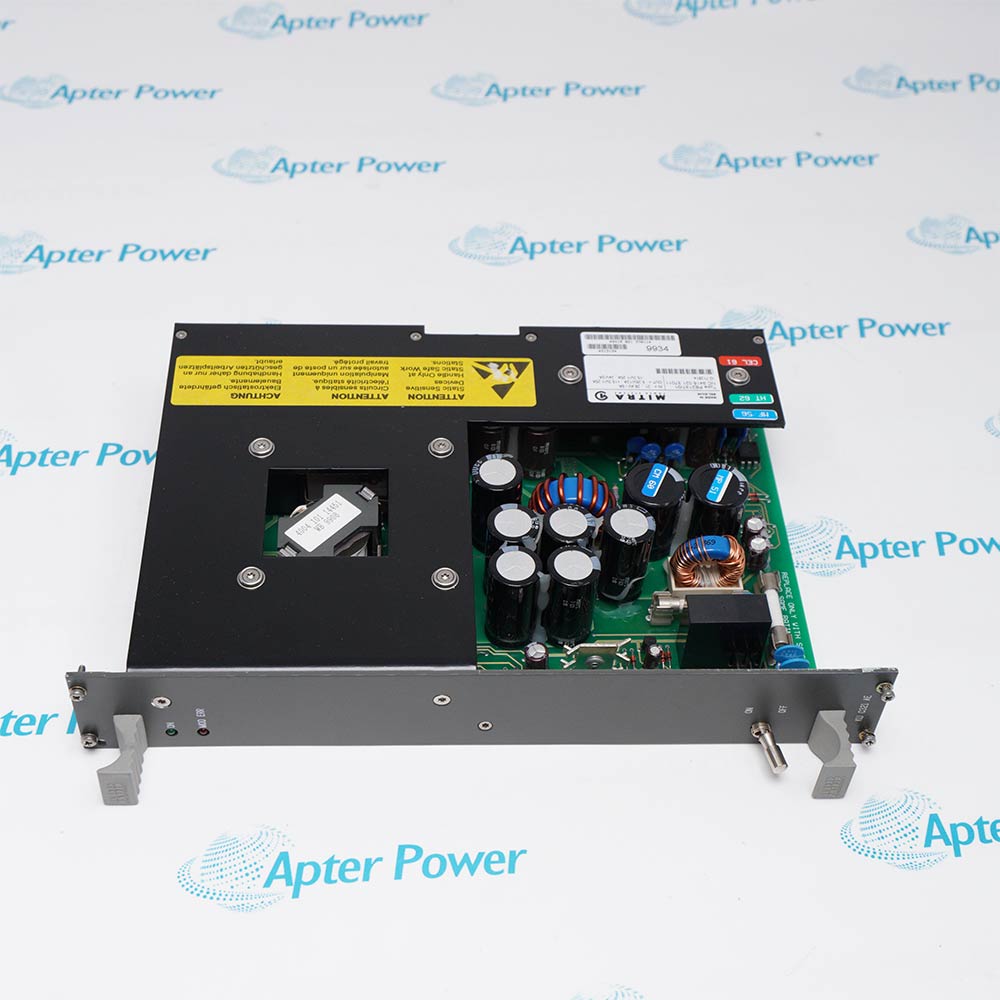
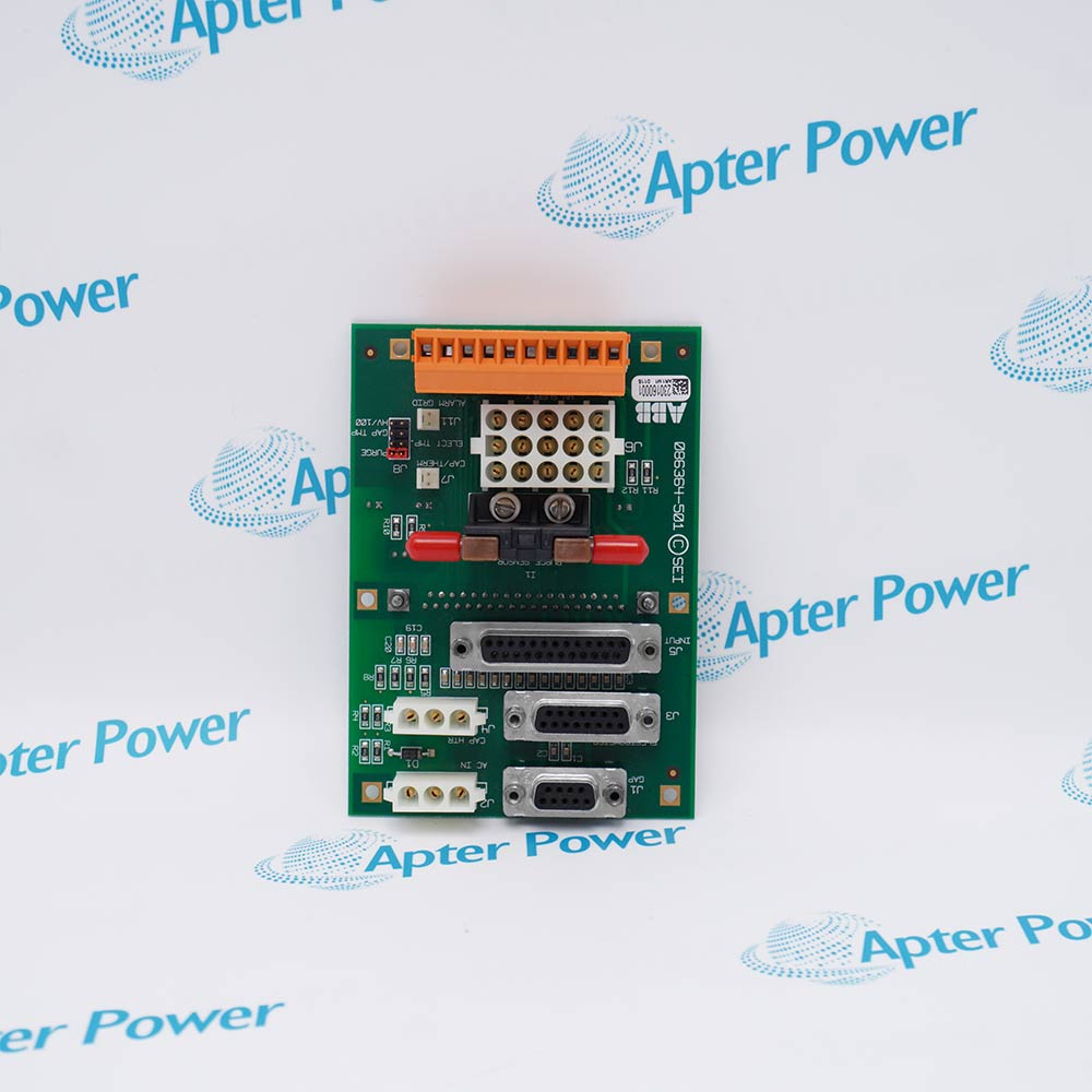
The Elsag Bailey IEMMU01 is a Module Mounting Unit in the INFI 90 AC modular power and control-system architecture. It provides mechanical housing, power connections and signal interconnections for power-supply and process-control modules.
- IEMMU01 Module Mounting Unit
- INFI 90 AC Modular Power System
- Housing, power connections and module signals
- Alternative mounting approach to the rear-mounted IEPMU01
The mounting unit supports and interconnects installed modules in the cabinet. It distributes the system power rails and module signals through the documented backplane arrangement; it does not itself measure or drive process signals.
Important Notice: Keep the complete IEMMU01 marking unchanged and verify the physical nameplate, revision, companion hardware, and current ABB/Elsag Bailey documentation before installation or replacement.
Apter Power IEMMU01 Manuals and Guides
Important Notice: These are two separate Apter Power documents prepared from the official ABB/Elsag Bailey source named in each document. Confirm the physical nameplate, current manufacturer documentation, and applicable installation or system drawing before installation or replacement.
Control System Integration
Main control cabinets requiring a common mounting and interconnection chassis for INFI 90 power and process modules.
Signal and Data Handling
Backplane power and module interconnection signals; field I/O is handled by the installed process modules and their termination hardware.
Companion Hardware
INFI 90 power modules, process-control modules, cabinet cooling, approved wiring and mounting hardware.
Commissioning and Verification
Use IEMMU01 only after confirming its complete nameplate, revision, configuration, connections, and affected system functions.
Read and follow the official manufacturer source and applicable installation instructions before use. Verify the exact complete ordering code from the physical nameplate.
1
Do not assign individual power-module output ratings to the IEMMU01; verify the installed power-module combination.
2
Maintain the cabinet airflow and environmental limits stated in the AC modular power-system manual.
3
Isolate power and document every module position and connector before chassis service.
4
Observe the applicable wiring, grounding, approval, environmental, and enclosure requirements.
5
Record the complete model, revision, configuration, and commissioning results before returning the system to service.


 Videos
 News
News Applications