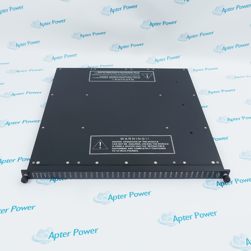
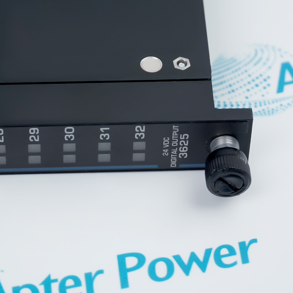
Provides a fault-tolerant output path between the Tricon control logic and final field devices in safety and critical-control loops.
- Signal or energy path: Triplicated commands are voted within the output architecture before the selected state is applied to the field circuit; supervision supports fault detection without redefining the configured trip philosophy.
- Companion components: Use only the approved Tricon chassis, termination hardware, field cabling and project-specific load circuits.
- Engineering check: Commissioning must verify the trip philosophy, diagnostic coverage, load presence and documented fail-safe state.
- System boundary: The configured safety application and field-termination design determine the final energize-to-trip or de-energize-to-trip behavior.
Industrial application,emergency shutdown, burner management, turbine protection and other process-safety systems.
Important Notice: Verify the complete TRICONEX 3625 nameplate, installed-system documentation, companion hardware and current Triconex instructions before installation or replacement.
Apter Power TRICONEX 3625 Manuals and Guides
Important Notice: The first link is the product-parameters PDF prepared only from the cited manufacturer information; the second link is the Apter Power product manual. Confirm the physical nameplate, current manufacturer documents, and host-system requirements before installation or replacement.
Emergency shutdown outputs
Commands compatible shutdown relays, solenoids or isolation devices in a configured Tricon safety function.
Fire and gas protective outputs
Provides supervised DC output circuits for compatible alarms, deluge interfaces or ventilation shutdown functions.
Burner and combustion safeguards
Supports configured energize-to-trip or de-energize-to-trip output circuits for critical fuel and combustion equipment.
Turbine and process protection
Drives compatible trip and interlock loads in high-availability process-safety systems.
Read and follow the current Triconex / Schneider Electric documentation and host-equipment instructions before work. Verify the complete physical nameplate and system configuration.
1
Use qualified safety-system personnel and follow the current Tricon planning, installation and field-termination documentation.
2
Verify that the controller is version 10.2 or later and that the exact chassis, firmware and TriStation project support model 3625.
3
Select two compatible 16-point termination products and confirm field voltage, load current, inrush current, wiring and supervision thresholds.
4
Do not remove or replace hardware in a hazardous location unless the area is known to be free of ignitable gas concentrations and the applicable approval permits the work.
5
Validate every safety function, point state, diagnostic alarm and final element before returning the process to service.