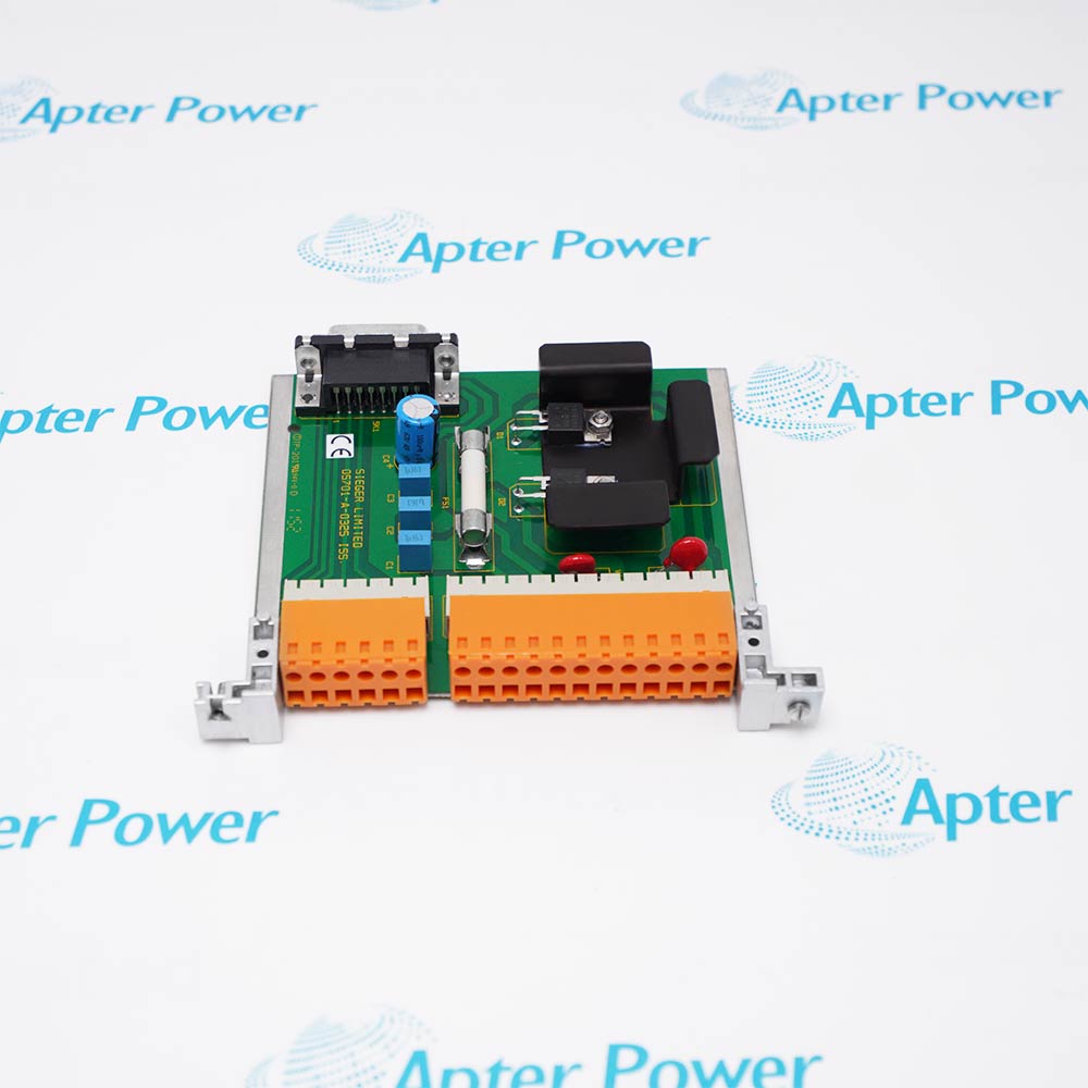
Honeywell MC-TAMT03 51309223-175 is a field termination assembly for LLMux thermocouple signal wiring.
- LLMux thermocouple termination
- Temperature-signal marshalling
- Cabinet-side field routing
- System-specific terminal integration
MC-TAMT03 provides the termination path for the installed LLMux thermocouple measurement channels. Maintain thermocouple polarity, alloy pairing, shield routing and the specified cold-junction arrangement, then compare channel readings with the expected process condition after wiring.
Important Notice: Confirm whether the matching I/O module, terminal assembly, cable set, field wiring and cabinet accessories required for MC-TAMT03 51309223-175 are included in the quotation or stock description.
Apter Power MC-TAMT03 Manuals and Guides
Important Notice: These are two separate Apter Power documents prepared from product-specific Honeywell technical information. Confirm the physical nameplate, current Honeywell documents and installed-system requirements before configuration or installation. They do not replace Honeywell manuals.
MC-TAMT03 installed-base replacementSupports like-for-like maintenance of the documented LLMux thermocouple field termination assembly.
MC-TAMT03 compatibility reviewChecks the host hardware, slot or mounting position, companion assembly, cable and revision before replacement.
MC-TAMT03 installation planningDefines the required isolation, ESD, terminal, wiring and configuration checks before field work.
MC-TAMT03 commissioningSupports controlled power, channel, communication, diagnostic and process-response checks after installation.
Read the applicable Honeywell instructions before work. Verify model MC-TAMT03, part number 51309223-175 and the installed-system configuration.
1Verify model MC-TAMT03 and part number 51309223-175 on the physical label before use.
2Use MC-TAMT03 with the exact Honeywell host, companion hardware, terminal assembly and field wiring specified for the installed system.
3Match every MC-TAMT03 connector, terminal, cable and companion assembly before moving field wiring.
4Back up the applicable controller, node, I/O or communication configuration before replacing MC-TAMT03.
5Isolate energy before handling MC-TAMT03 unless the applicable hardware procedure explicitly permits energized service.
6Follow ESD controls and protect MC-TAMT03 connectors and printed-circuit assemblies during handling.
7Do not transfer channel, voltage, current, terminal or firmware values from a similar model to MC-TAMT03.
8After installing MC-TAMT03, complete the relevant power, channel, link, diagnostic, alarm and fail-state checks.