Yokogawa transmitters sit at some of the most critical points in an industrial power system. They watch battery strings in UPS rooms, cooling water on inverter heat exchangers, fuel supply pressure for generators, and busbar temperatures on mission-critical switchgear. When those transmitters are paired with incompatible sensors, analog input modules, or wireless and safety components, the result is not just a bad reading; it can be nuisance trips, hidden overloads, and eventually unplanned outages.
From a reliability perspective, the transmitter itself is rarely the weakest link. Most of the failures I see in the field come from the components around it: mismatched sensors, underspecified input cards, or thirdŌĆæparty modules bolted on without a proper engineering cross-check. This guide walks through how to select and cross-reference compatible parts around Yokogawa transmitters, drawing on practices documented by instrument manufacturers, analog input specialists, and RF and regulatory guidance, and translating them into a practical workflow you can use in real projects.
What ŌĆ£Compatible PartsŌĆØ Really Means Around a Yokogawa Transmitter
Compatibility is not just a question of thread size or whether a connector physically mates. Around a Yokogawa transmitter you are dealing with four overlapping dimensions of fit.
The first dimension is signal and power interface. Most pressure and temperature transmitters, including those described in Foxboro and Rosemount manuals, output a standard 4ŌĆō20 mA current loop. Some systems also use 0ŌĆō10 V or other analog ranges, as described by PPI India in their guidance on analog input modules. A compatible analog input card or safety barrier must accept exactly the signal type the transmitter produces, and your power supply must be able to energize a loop-powered device within its specified voltage and load limits.
The second dimension is the sensor side. For temperature loops, Endress+Hauser shows how real RTDs deviate from the ideal curve and how sensorŌĆōtransmitter matching using the CallendarŌĆōVan Dusen equation can tighten accuracy when you combine a specific RTD with a specific transmitter. Even if you are not using that exact algorithm, the lesson is that you cannot treat the sensor as a generic part. Its resistance, tolerance class, and calibration range must be compatible with how the transmitter expects to interpret the signal.
The third dimension is mechanical and environmental fit. Manuals for Foxboro pressure transmitters and Rosemount 248 temperature transmitters emphasize mounting orientation, vibration, ambient temperature, and ingress protection. If you bolt a Yokogawa head-mounted transmitter into a connection head that cannot keep it dry in a washdown area, or you park a DIN-rail temperature transmitter in a panel that runs hotter than its rating, no amount of electrical compatibility will save you from drift and early failures.
The fourth dimension involves digital, wireless, and regulatory interfaces. When transmitters are tied into wireless links or remote I/O, you need to respect guidance from RF module and transmitter-module documents as well as 47 CFR Part 15 rules from the Federal Communications Commission. Certified RF modules have to be integrated and labeled correctly, antenna gains must stay within the grant conditions, and the host device must still pass unintentional-emissions limits. Ignoring those constraints can turn a clean Yokogawa loop into a compliance problem.
In practice, a ŌĆ£compatible partŌĆØ is therefore one that meets all four dimensions simultaneously: it speaks the same electrical language, interprets the sensor correctly, survives the physical environment, and fits the regulatory envelope of the overall device.
The Measurement Chain Around a Yokogawa Transmitter
Engineers often think of a transmitter as a single box tagged on a P&ID, but for compatibility work it is more helpful to see the entire chain from the primary process variable to the controller input. GlobalSpecŌĆÖs overview of sensor transmitters is useful here because it breaks the problem down into how raw sensor outputs are conditioned, scaled, and converted into standard signals.
Around a typical Yokogawa process transmitter in a power room, you will encounter at least these elements: a primary sensor or primary element, the transmitter, any isolation valves or manifolds for pressure devices, loop and trunk cabling, optional intrinsic safety barriers or isolators, the PLC or DCS analog input module, and sometimes a wireless or remote I/O hop layered on top.
You can think of each element as adding gain, error, latency, or noise. GlobalSpec models a sensorŌĆōtransmitter pair with a transfer function that includes a gain factor and a time constant. The same concept extends when you include the cabling, input module, and ADC in a PLC card governed by test methods like those in IEEE 1241. Every extra conversion and interface has a specification. If you cross-reference parts so that each device is operating in the middle of its own range, you reduce the chance that those specifications stack up in the wrong direction.
The table below summarizes these elements and the compatibility questions you should be answering from the Yokogawa datasheet outward.
| Chain Element | Compatibility Focus | Relevant Guidance Source |
| Sensor or primary element | Type, range, tolerance, calibration method | Industrial temperature and pressure manuals, Endress+Hauser notes |
| Yokogawa transmitter | Input types, output signal, supply, ambient rating | Foxboro and Rosemount transmitter manuals for analogous devices |
| Manifold or impulse piping | Pressure rating, materials compatibility, vent/drain features | Typical Foxboro pressure transmitter installation guidance |
| Intrinsic safety barrier/isolator | Loop voltage drop, entity parameters, fault energy limits | General hazardous-area practices and vendor barrier datasheets |
| Cabling and terminations | Gauge, shielding, separation from noise sources | Common 4ŌĆō20 mA wiring practices from Foxboro and Rosemount docs |
| PLC/DCS analog input module | Input type, resolution, accuracy, sampling rate, count | PPI India and GlobalSpec on analog input and sensor transmitters |
| Wireless or RF module (if used) | Band, power, antenna, certification, labeling | FCC Part 15, FCC and RF-module integration guidance |
Once you see the chain laid out this way, the logic of cross-referencing parts becomes clearer. Rather than hunting for vendor AŌĆÖs ŌĆ£equivalentŌĆØ to a Yokogawa accessory in isolation, you work parameter by parameter through the chain.
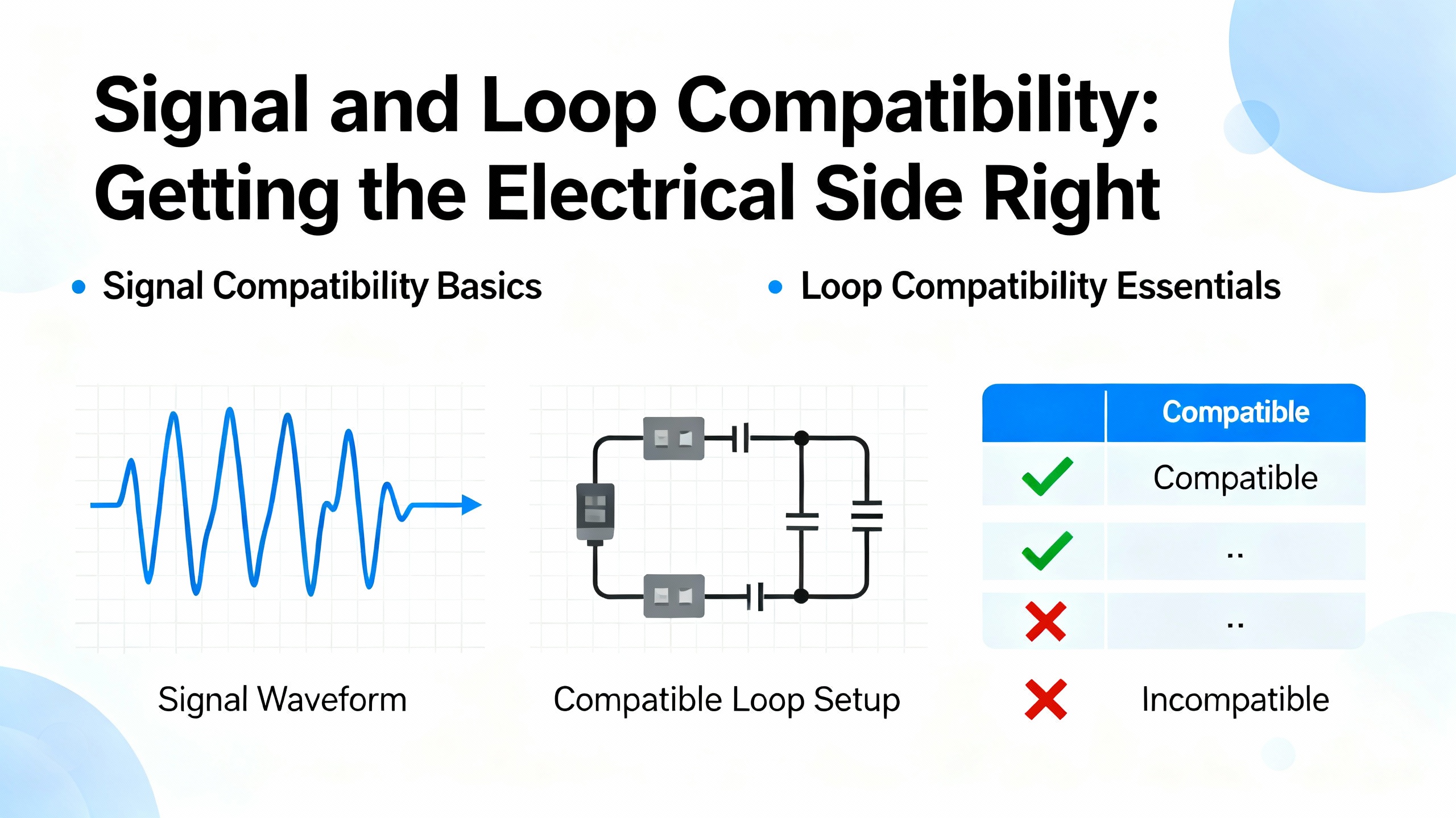
Signal and Loop Compatibility: Getting the Electrical Side Right
Most industrial transmitters discussed in Foxboro and Rosemount documentation are two-wire, loop-powered devices that use a 4ŌĆō20 mA current loop. The same is true for many Yokogawa models used in power plants. On the receiving end, PPI IndiaŌĆÖs guidance on analog input modules highlights the importance of signal compatibility as the very first selection criterion: you must know whether the module expects current, voltage, resistance, or another quantity.
When you cross-reference an existing Yokogawa loop to a new input card, these are the practical checks to make.
The first step is to confirm the output signal of the transmitter. If the Yokogawa model is configured for 4ŌĆō20 mA, the analog input module must support 4ŌĆō20 mA on that channel and should be configured to treat the signal as active current, not as a passive voltage. If the loop is built around 0ŌĆō10 V or another range, the input module must be able to accept that voltage with adequate headroom.
Next, you should look at resolution and accuracy on the receiving side. PPI IndiaŌĆÖs article emphasizes resolution as the smallest change in input the module can detect and accuracy as how closely the reported value matches reality. If the Yokogawa transmitter offers high reference accuracy, there is no point pairing it with a coarse input module that quantizes the signal so badly that small process changes vanish into the least significant bit. You do not need to quote every dB of effective number of bits as defined in IEEE 1241, but you should at least ensure that the input moduleŌĆÖs resolution is fine enough that transmitter accuracy, not ADC quantization, dominates your error budget.
Supply voltage and loop load also matter. Loop-powered transmitters require a certain minimum voltage across their terminals to operate correctly, after you subtract the voltage drops across barriers, long cable runs, and the internal burden resistor of the input card. RosemountŌĆÖs 248 manual, for example, describes a DC supply window and loop-load limits for reliable 4ŌĆō20 mA operation. When you swap or cross-reference power supplies or barriers around a Yokogawa transmitter, you should calculate the loop voltage budget so that the supply, at its lowest normal voltage, still leaves enough across the transmitter to keep it in its specified region.
Finally, consider input dynamics. PPI India notes that sampling rate must match the speed of the process. If your UPS monitoring system uses Yokogawa transmitters to catch fast DC ripple or pressure spikes during transfer events, a slow input module that samples only occasionally may miss those excursions. Conversely, for slow variables such as room temperature or tank level, a modest sampling rate is adequate, but you may want damping in the transmitter to avoid sharing every small fluctuation with the control system.
Sensor and Transmitter Matching: Especially Critical for Temperature
Temperature measurement in power systems is a special case because it is often the earliest warning of trouble: inverter heatsinks, transformer windings, battery rooms, and generator exhausts all rely on accurate sensors. The Endress+Hauser material on sensorŌĆōtransmitter matching shows why just swapping in any Pt100 RTD beneath a Yokogawa transmitter is not ideal if you care about ŌĆ£last digitŌĆØ accuracy.
In theory, a standard Pt100 has a precise resistanceŌĆōtemperature curve with a nominal 100 ohms near the freezing point of water and about 138.5 ohms near the boiling point under standard pressure. In practice, real sensors deviate from that curve, and tolerance classes such as Class A and Class B define how far they are allowed to wander. Endress+Hauser describes this as a widening funnel of possible error as temperature goes up.
Their approach is to calibrate the specific sensor at a series of temperatures, often three or five points, then derive sensor-specific coefficients for the CallendarŌĆōVan Dusen equation. Those coefficients are written into the transmitter so it no longer assumes the ideal curve; it uses the actual behavior of that sensor. Within the calibrated range, the error band becomes narrow and nearly constant instead of widening.
You may not have a Yokogawa transmitter that supports uploading such coefficients directly, but the principles still apply to compatible parts selection. If you replace a calibrated RTD with a cheaper, generic probe, you are breaking the implicit sensorŌĆōtransmitter matching, and you should expect more measurement error. If you cross-reference a Yokogawa temperature transmitter to a different sensor, pick one with at least the same or better tolerance class, similar construction, and a calibration certificate where possible.
Endress+Hauser also warns that once you have performed sensorŌĆōtransmitter matching, the two become a pair. Replacing only the measuring insert or only the transmitter destroys that pairing and makes results unpredictable. When you cross-reference parts in critical temperature loops, treat matched pairs as single assets in your spares strategy.
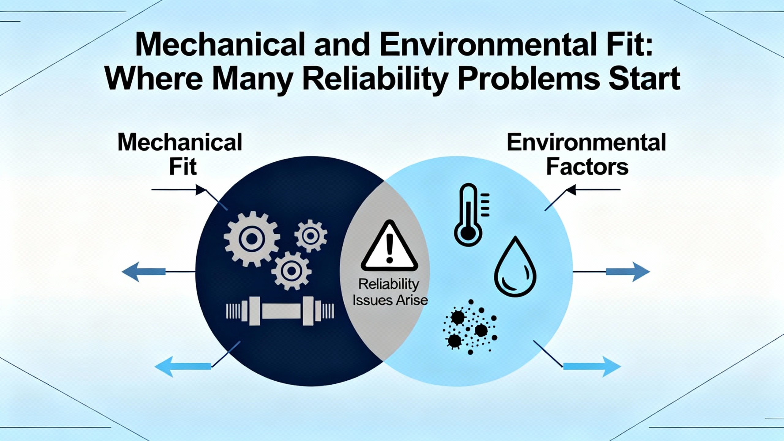
Mechanical and Environmental Fit: Where Many Reliability Problems Start
Foxboro pressure transmitter manuals and the Rosemount 248 documentation repeatedly point out that installation and environment can ruin a good instrument. The same holds for Yokogawa transmitters.
Mechanically, you must match thread types, pressure ratings, and materials. An isolation manifold rated for a lower pressure than the Yokogawa transmitter or the process line is not compatible, even if it screws together perfectly. Transmitters designed for clean process fluids may not survive slurries or corrosive gases without appropriate seals and impulse piping, which Foxboro manuals address through detailed guidance on orientation, venting, and draining.
Environmentally, most head-mounted temperature transmitters and compact pressure devices are rated for ambient temperatures somewhere in the broad neighborhood from about minus forty degrees up to around one hundred seventy or one hundred eighty degrees Fahrenheit, based on ranges described in Rosemount 248 material and RF module datasheets. If your UPS power room or inverter gallery routinely runs near the upper end of that range, and you tuck a transmitter into a poorly ventilated junction box, the local temperature can exceed its rating even though the room itself is within limits. When cross-referencing enclosures, cable glands, and mounting locations, check that the combination keeps the transmitter within its ambient rating.
Vibration is another mechanical compatibility variable. Transmitters intended for mounting on piping can tolerate a certain level of vibration, but DIN-rail units sitting in a lightly braced panel next to big inverters may suffer more. Foxboro manuals recommend orienting and supporting transmitters and impulse lines to minimize vibration and resonances. When you change mounting hardware or support points, you are changing that vibration environment and potentially reducing life.
Wireless, Digital, and Regulatory Interfaces
As plants modernize, more Yokogawa loops are extended via wireless backhaul or remote I/O, especially for non-safety-critical monitoring of UPS rooms, remote substations, and rooftop equipment. The moment you add a 2.4 GHz module or any other radio around a transmitter, you take on a new set of compatibility constraints that go beyond ŌĆ£does it talk Modbus.ŌĆØ
The NiceRF guidance on 2.4 GHz modules is a good illustration. Those modules operate in the 2.4 GHz industrial, scientific, and medical band and cover a range of data rates and output powers. Some models based on Nordic nRF24 chips target shorter-range, higher-speed links from roughly under two kilobits per second up to a few megabits per second. Others based on Semtech LoRa devices trade data rate for extreme sensitivity, with receiver figures down to about minus one hundred thirty-two decibels-milliwatt at the lowest rates, enabling long-range links. That variety means that if you cross-reference a wireless module around a Yokogawa transmitter, you must match not only voltage and interface but also link budget and required range for your site.
Regulatory compatibility is governed largely by FCC Part 15 in the United States, as summarized in the Code of Federal Regulations and in FCC workshop material on unlicensed transmitters and transmitter modules. Unlicensed devices are allowed to operate without individual user licenses only if they meet strict emission and operational limits and accept interference. Guidance on transmitter modules describes full modular approvals and limited modular approvals, antenna constraints, and labeling rules. If you integrate a certified RF module into a host that includes a Yokogawa transmitter, you must respect the conditions of that moduleŌĆÖs approval and ensure that the finished assembly still meets emissions limits as an unintentional radiator.
Specialized RF compliance guidance emphasizes that altering antennas, adding external RF amplifiers, or changing the ground plane can invalidate a moduleŌĆÖs certification and trigger new testing or filings. In a power plant context, that means you cannot casually swap a panel antenna for a higher-gain whip on the roof just to improve coverage for a Yokogawa loop, unless you have confirmed it is permitted by the moduleŌĆÖs grant or you plan to recertify.
From Datasheet to Cross-Reference Matrix: A Practical Workflow
In real project work, compatibility is easiest to manage when you treat the Yokogawa transmitter as your fixed reference and derive all other parts from its specification sheet.
The first task is to gather the transmitter datasheet and installation manual. Manuals from vendors such as Foxboro and Rosemount show what you can expect: detailed tables for measurement range, output signal type, supply voltage limits, operating ambient and process temperatures, and hazardous-area approvals. Yokogawa documentation follows the same pattern. Extract every parameter that refers to an interface with another device: sensor input type, output signal type, power supply range, maximum loop load, ambient rating, enclosure rating, and communication protocols if it is a smart transmitter.
The next task is to characterize the connected components. For the sensor, record the type, range, and tolerance. Endress+HauserŌĆÖs sensorŌĆōtransmitter matching material reminds you to pay attention to calibration data and tolerance classes, not just nominal type. For manifolds, note pressure rating and materials. For barriers and isolators, capture maximum voltage drop, current rating, and entity parameters. For analog input modules, use the PPI India checklist: input signal type, resolution, accuracy, sampling rate, channel count, and environmental ratings. For wireless modules, capture band, output power, receiver sensitivity, certification type, and antenna gain.
Once you have these specifications, you can build a simple cross-reference matrix. Rather than relying on vendor comparison charts that may not match your use case, you fill in each column based on parameters you have actually checked.
Here is an example of what such a matrix might look like for the electrical side of the loop.
| Yokogawa Transmitter Output | Compatible Input / Module Characteristics | Evidence Basis |
| 4ŌĆō20 mA loop, loop-powered | Analog input module explicitly rated for 4ŌĆō20 mA; adequate resolution and accuracy; loop supply and burden allowing required voltage across the transmitter | PPI India, GlobalSpec, Rosemount 248 |
| 0ŌĆō10 V analog | Input module with 0ŌĆō10 V range; input impedance high enough not to load the transmitter; noise performance suited to wiring distance | PPI India and GlobalSpec |
| RTD input (e.g., Pt100) | Sensor of same nominal type and wiring scheme; equal or better tolerance class; calibration range matching transmitter configuration | Endress+Hauser sensorŌĆōtransmitter matching notes |
| Digital or RF backhaul | RF module with compatible interface; certified for intended band and power; antenna and labeling complying with module documentation and Part 15 guidance | FCC Part 15 and RF-module guidance |
You can build similar tables for mechanical and environmental compatibility. For example, for each transmitter you can list its ambient temperature range, enclosure type, and process connection, then cross-reference enclosures, glands, and manifolds that meet or exceed those values. That approach makes it much easier for design teams to see at a glance which parts can be paired safely.
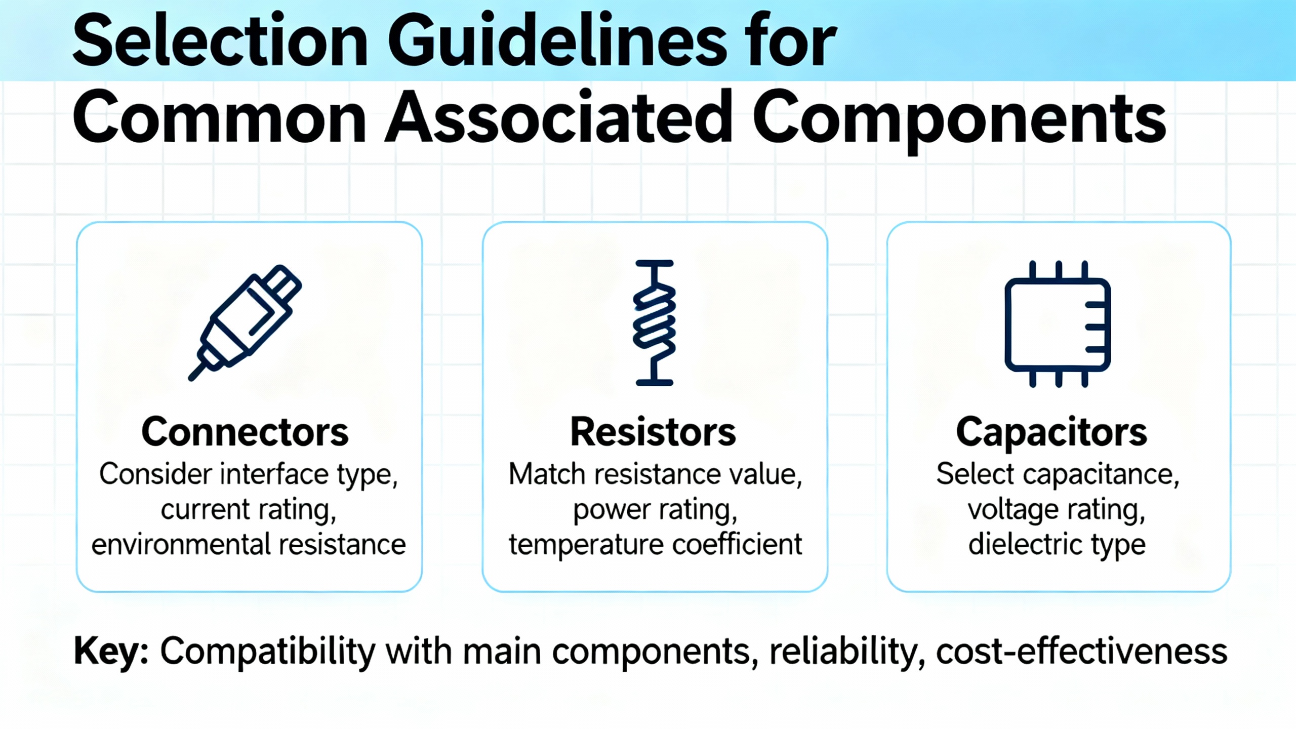
Selection Guidelines for Common Associated Components
Some associated components appear in almost every Yokogawa-based loop in a power or industrial plant. The most common are analog input modules and PLC or DCS cards, isolators and intrinsic safety barriers, and, increasingly, wireless or remote I/O modules. Using the research-backed criteria from PPI India, GlobalSpec, instrument manuals, and RF guidance, you can establish vendor-neutral rules for what qualifies as a ŌĆ£compatibleŌĆØ part.
For analog input modules, the core checks are signal type, range, resolution, accuracy, sampling rate, channel count, and environment. PPI India stresses that you should first ensure that the module accepts the signals your sensors and transmitters produce, whether that is 4ŌĆō20 mA, 0ŌĆō10 V, or other formats. GlobalSpec adds useful definitions of range, span, and zero: range is the minimum to maximum measurand, span is the numerical difference, and zero is the low-end value of the range, which is not always actual zero. When you choose an input card for a Yokogawa transmitter with a particular calibrated range, you should confirm that the cardŌĆÖs input range brackets that output and that span-to-resolution is sufficient to resolve meaningful changes in the process variable.
Isolators and intrinsic safety barriers must be selected with the loop voltage and power budget in mind. Manuals for Foxboro and Rosemount transmitters show typical voltage budgets and stress the importance of suitable barriers in hazardous areas. Each barrier adds a voltage drop and a limit on maximum loop current. If you cross-reference one barrier for another around a Yokogawa loop, make sure the new barrierŌĆÖs voltage drop and fault-energy ratings still permit the transmitter to operate within its supply window and maintain its hazardous-area approvals.
For wireless and remote I/O modules, the selection criteria broaden. NiceRFŌĆÖs catalog of 2.4 GHz modules illustrates how different devices trade power, sensitivity, data rate, and current consumption. If you are carrying Yokogawa transmitter data over a long span in a plant with a lot of steel and concrete, choosing a module with higher receiver sensitivity and, where permitted, higher output power gives you more margin. However, you must stay within what Part 15 allows for unlicensed operation, and you must keep to the antenna types and gains listed in the moduleŌĆÖs certification documents. FCC guidance on transmitter modules also reminds integrators that the finished host must still meet unintentional-emissions limits and that certain changes can force a new certification.
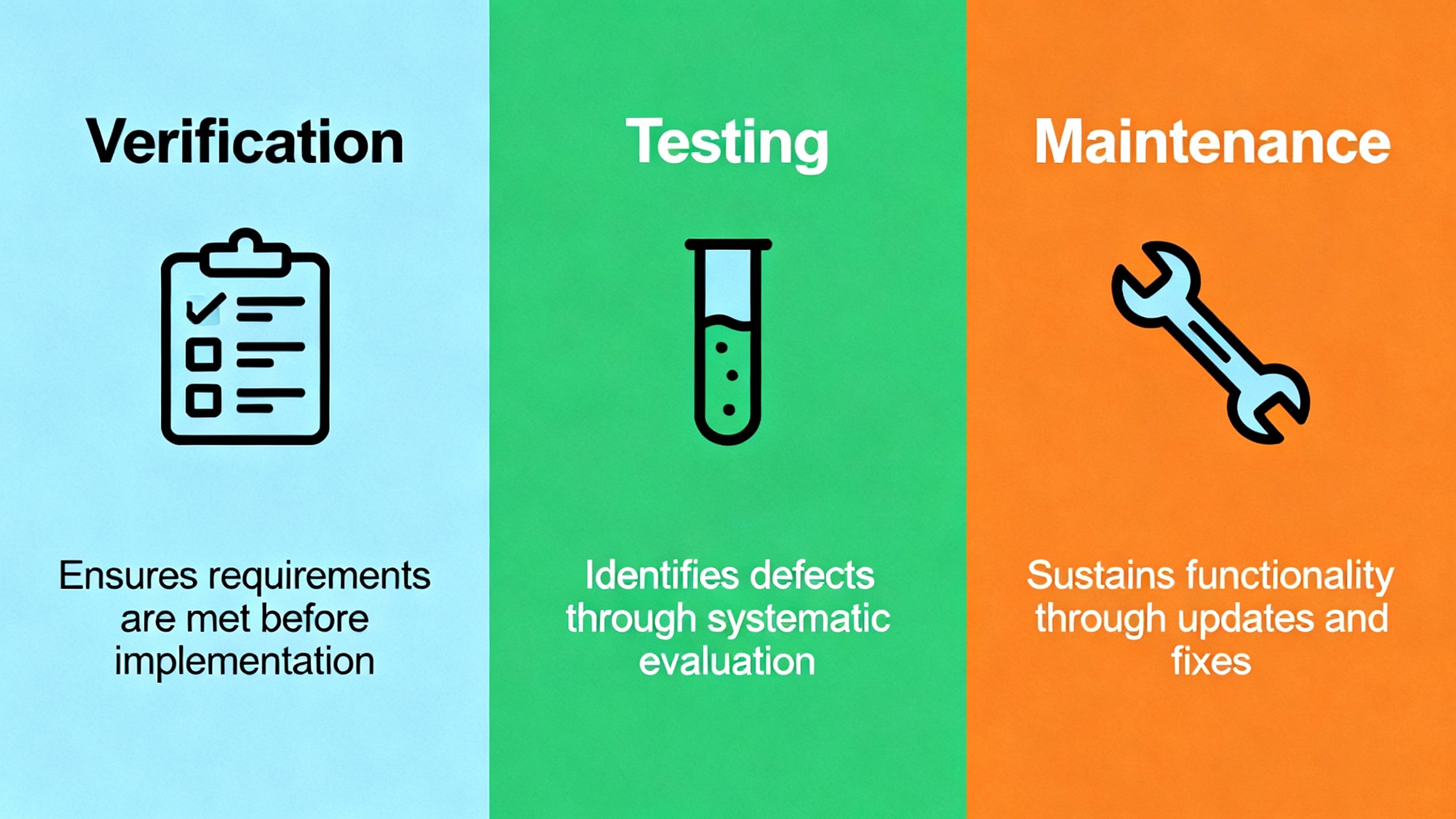
Verification, Testing, and Maintenance
Even a well-designed compatibility matrix is only as good as the verification and maintenance practices that back it up. Manuals from Foxboro and Rosemount emphasize periodic visual inspection and calibration checks, often annually or more frequently for critical loops. Those practices should extend beyond the transmitter to the parts you have cross-referenced.
When you replace an input module, barrier, or sensor around a Yokogawa transmitter, you should perform a loop check that confirms the 4ŌĆō20 mA circuit is behaving as expected. That usually means applying known pressures or temperatures with a calibrator, adjusting zero and span if needed, and verifying that the receiving system sees the correct signal at zero, mid, and full scale. Foxboro guidance suggests checking at 0 percent, 50 percent, and 100 percent points. If the receiving PLC analog card now has a different scaling or resolution, your indication at the control system may differ even if the transmitter is perfect; that is a compatibility issue that should be caught during commissioning.
On the RF side, best practice from RF module integration guidance is to perform pre-scan emissions checks on early prototypes and document antenna types, gains, and separation distances. Even if you are reusing an existing certified RF module, changing the way you mount it near a Yokogawa transmitter, or routing cables differently, can alter emissions and susceptibility.
Maintenance records should capture not only transmitter calibration data but also changes to surrounding components. If you swap a sensor in a matched pair, that should be noted. If you replace a barrier, record its model, entity parameters, and date of installation. Over time, these records let you see whether a particular combination of transmitter and associated parts is more prone to drift or failure, guiding future cross-reference decisions.
Short FAQ
Can I mix non-Yokogawa sensors with Yokogawa transmitters without issues? You can, but only if the sensorŌĆÖs type, range, wiring scheme, and tolerance class match what the transmitter expects, and ideally if you calibrate the pair together. Guidance on sensorŌĆōtransmitter matching from Endress+Hauser shows that even small deviations in RTD curves can cause systematic errors unless they are compensated. For critical temperature loops around UPS and inverter equipment, you should treat the sensor and transmitter as a matched combination rather than swapping one independently.
How do I know if my PLC analog input card is ŌĆ£good enoughŌĆØ for a high-accuracy Yokogawa transmitter? Use the criteria suggested by PPI India and GlobalSpec. Confirm that the input card accepts the transmitterŌĆÖs output signal type, that its input range covers the transmitterŌĆÖs calibrated span, and that its resolution and accuracy are fine enough that the transmitterŌĆÖs own error is the dominant contributor. If the input card quantizes the signal too coarsely or adds significant noise, upgrading the transmitter alone will not improve your overall measurement.
What should I watch for when adding wireless links to existing Yokogawa loops? Treat the RF module as another component that must be compatible in power, interface, and regulation. Draw on NiceRF data for band, output power, and sensitivity to ensure the module can cover your required distance, but also respect FCC Part 15 and transmitter-module guidance on antenna types, gains, and labeling. Changing antennas, raising power, or embedding the module differently can force additional testing or new approvals, even if the original module is certified.
In power-critical environments, a Yokogawa transmitter is only as reliable as the parts surrounding it. When you approach compatibility as a structured, evidence-based cross-reference exercise instead of a trial-and-error process, you protect not just your measurements, but the uptime of every UPS, inverter, and critical load those measurements are meant to safeguard.
References
- https://campserv.emory.edu/_includes/documents/2024_design_standards_and_guidelines.pdf
- https://facilities.gatech.edu/system/files/forms_files/Yellowbook-202204.pdf
- http://class.ece.iastate.edu/djchen/ee509/2018/IEEE1241-2011.pdf
- https://campus.kennesaw.edu/offices-services/planning-construction/docs/d-c-standards-and-appendix-combined.pdf
- https://nvlpubs.nist.gov/nistpubs/ir/2017/nist.ir.8118r1.pdf
- https://fod.osu.edu/sites/default/files/div_40.pdf
- https://admisiones.unicah.edu/Resources/9tBp3d/1OK026/foxboro_pressure_transmitter_manual.pdf
- https://www.cdfa.ca.gov/dms/programs/Publications/FRM/2018/6-2018_FRM_Chapter_1_Part_6_Article%202-2.3.pdf
- https://www.dartmouth.edu/fom/standards_policies/resources_standards/guidline_storage/23_09_23_automatic_temperature_controls.pdf
- https://www.ecfr.gov/current/title-47/chapter-I/subchapter-A/part-15


 Videos
 News
News Applications


Leave Your Comment