Why a Pressure Transmitter Datasheet Matters to Power and Reliability Engineers
In industrial and commercial power systems, we spend a lot of time talking about UPS runtime, inverter efficiency, and protection coordination. Yet the stability of those systems often depends on something much more basic: whether the plantŌĆÖs pressure measurements are trustworthy. Boiler drum level, condenser vacuum, fuel gas pressure to turbines, lube oil skid pressures, cooling water flow derived from differential pressure ŌĆō if those measurements drift or fail, your ŌĆ£five ninesŌĆØ power supply target starts to look optimistic.
That is where the pressure transmitter datasheet becomes a reliability document, not just a procurement form. For Yokogawa transmitters in particular, the datasheet encapsulates accuracy, stability, safety integrity, environmental toughness, and diagnostic behavior. Reading it correctly is the difference between a pressure loop that quietly runs for a decade and one that repeatedly surprises you with trips and nuisance alarms.
In this article I will walk through the key parts of a Yokogawa pressure transmitter datasheet using information from Yokogawa product literature, selection guides from Ye┼¤il Grup Enerji, application summaries from Toprefine, and independent instrumentation references such as SMAR, BCST Group, AutomationForum, and specialized accuracy and dynamics articles from PMC, SensorsOne, Keller, Trafag, and others. I will keep the focus on what actually matters when you are specifying, commissioning, and maintaining transmitters in plants where power continuity and equipment protection are nonŌĆænegotiable.
Yokogawa Pressure Transmitter Families in Context
YokogawaŌĆÖs pressure lineup revolves around the EJA and EJX families and the DPharp digital sensor. Ye┼¤il Grup EnerjiŌĆÖs selection guide describes a broad range that covers gauge pressure models such as EJA530E and EJX530A, differential pressure types like EJA110E and EJX110A, absolute pressure models such as EJA310E, multivariable transmitters like EJX910A and EJX930A, diaphragm seal versions such as EJA118E for harsh media, hygienic models such as EJA560E and EJAC60E, and ISA100 wireless differential pressure transmitters like the EJXŌĆæB series.
A key technical point, supported by YokogawaŌĆÖs own product materials and by ToprefineŌĆÖs summary of the EJA family, is that these transmitters are built around the DPharp sensor. This is a digital resonant sensor developed in the early 1990s. By late 2016, Yokogawa reports that more than 11 million transmitters and calibrators using this technology had been installed worldwide, which is a substantial field history in real plants, not just in datasheets.
Typical headline numbers from Ye┼¤il Grup EnerjiŌĆÖs and ToprefineŌĆÖs documents include reference accuracies as tight as about ┬▒0.04% of reading for newer models and about ┬▒0.065% of span for the EJA110A differential pressure transmitter, with stability around 0.1% over five years for that model. YokogawaŌĆÖs own DPharp overview goes further and cites an unconditional longŌĆæterm stability guarantee of ┬▒0.1% for up to 15 years across operating conditions. For a power plant or industrial utility that wants to extend calibration intervals and avoid creeping setŌĆæpoint drift, those are not marketing niceties; they translate directly into fewer outages for calibration and less hidden error building up in your control loops.
From a powerŌĆæsystem perspective, I look at these families as building blocks. EJA110E or EJX110A devices handle boiler and process differential pressures, EJA310E takes care of absolute pressures in fuel gas or vacuum service, hygienic models support pharmaceutical plants that feed critical loads, and wireless EJX110B units can cover remote or hardŌĆæwiredŌĆæhostile locations without trenching. The datasheet is the map that tells you which device belongs where.

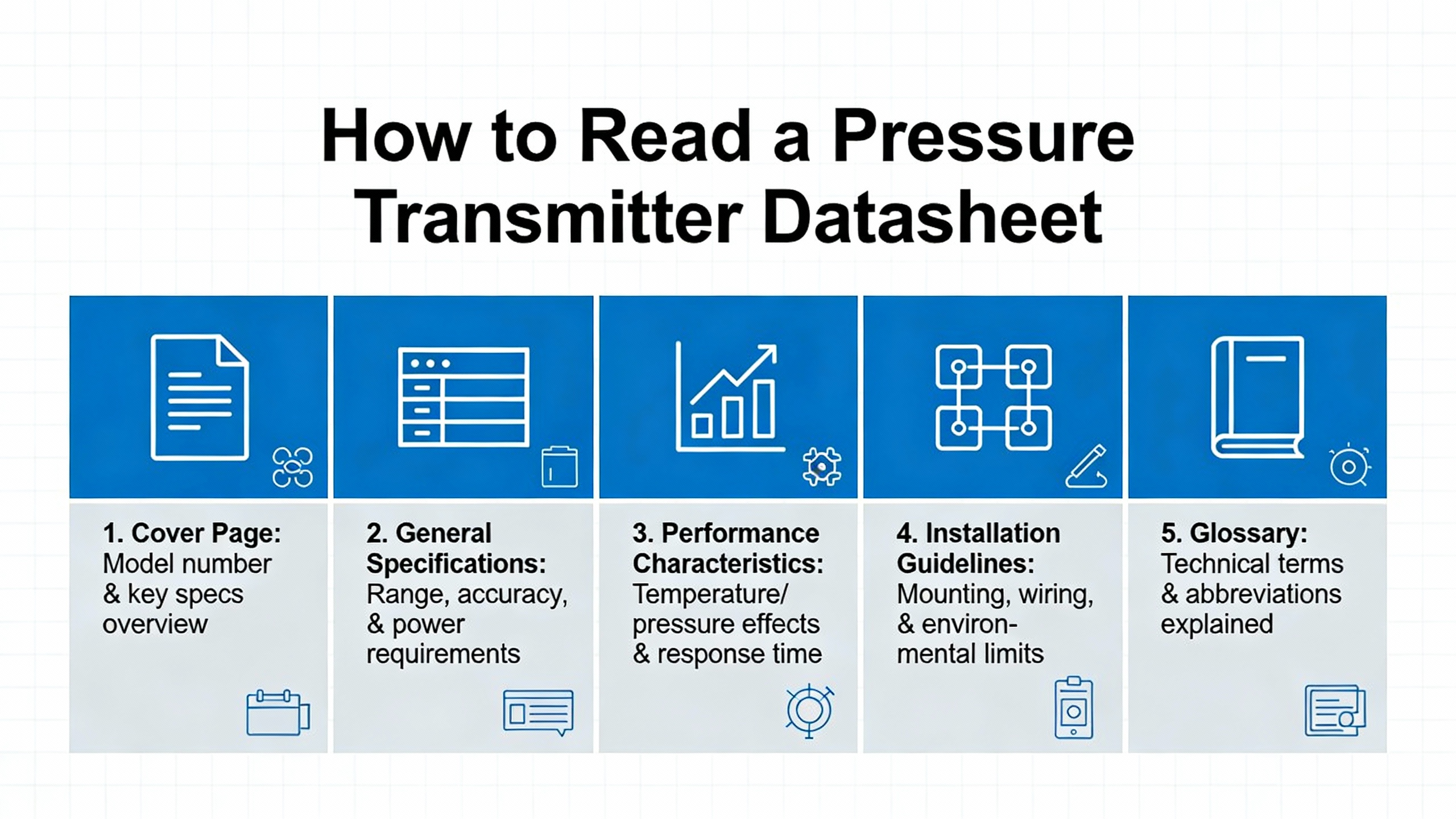
How to Read a Yokogawa Pressure Transmitter Datasheet
Instrumentation references from AutomationForum and BCST Group emphasize that a pressure transmitter datasheet is the primary reference for specifications, operating conditions, and limitations. For Yokogawa transmitters, the datasheet generally follows a structure that aligns with those best practices.
The first step is always confirmation. You verify that the datasheet title, manufacturer, and model code match what your design or purchase order calls for. With Yokogawa, that model code can be dense because it encodes pressure range, process connection, materials, communication protocol, diagnostics options, and approvals. Ye┼¤il Grup Enerji and Toprefine both stress using the model code tables alongside the datasheet to ensure you actually get, for example, an EJA110E with the right wetted materials and communication protocol.
Next, you interpret the measurement core. AutomationForum recommends checking the measuring principle and intended use, which for modern Yokogawa pressure transmitters will be a DPharp digital sensor accompanied by a brief explanation of whether the model is gauge, absolute, or differential. The Yokogawa ŌĆ£10 Questions ŌĆō Pressure TransmittersŌĆØ interview describes these reference types clearly: gauge pressure compares to local atmosphere, absolute pressure compares to a nearŌĆævacuum reference, and differential pressure compares two process points directly. The datasheet will explicitly indicate which type the device provides.
Then you move to pressure range and units. BCST Group points out that the normal operating pressure must sit comfortably within the calibrated span and below the deviceŌĆÖs upper range limit. Ye┼¤il Grup Enerji notes that Yokogawa spans run from about 0ŌĆō1 mbar up to 1,000 bar, which is roughly 0.015 psi up to about 14,500 psi. For a practical example, if you are measuring a condenser vacuum or lowŌĆæpressure gas line at around 3 psi, you do not want to select a transmitter range that tops out at several thousand psi; you would lose effective resolution. Instead, you would pick a range that centers your normal operating band somewhere between about 30 and 70 percent of the calibrated span.
Finally, you interpret performance and environment: accuracy, stability, response time, temperature and humidity limits, enclosure rating, hazardousŌĆæarea approvals, and so on. This is where most engineers get lost in the small print, yet it is also where most surprises originate if you skip it.
In the rest of this article I will unpack these pieces with specific Yokogawa examples.
Measurement Accuracy, Stability, and What Those Numbers Really Mean
Accuracy figures are often misunderstood. According to PMC and SensorsOne, pressureŌĆæsensor accuracy typically combines nonŌĆælinearity, hysteresis, and nonŌĆærepeatability into a single number, usually expressed as a percentage of full scale. Some manufacturers, including Yokogawa on certain highŌĆæend models, quote accuracy as a percentage of reading rather than span, which changes how the error behaves at low pressures.
For Yokogawa, Ye┼¤il Grup Enerji reports that many modern transmitters deliver accuracy around ┬▒0.04% of reading, while the EJA110A differential pressure transmitter is documented by Toprefine and a sample data sheet on Scribd as having reference accuracy of about ┬▒0.065% of span. That is already better than the ┬▒0.1ŌĆō0.5% of full scale that PMC describes as typical for industrialŌĆægrade transmitters, and it is significantly tighter than the ┬▒1% level that basic HVAC or utility monitoring might accept.
To see what this really means, consider a 0ŌĆō2500 psi transmitter similar to the example discussed by SensorsOne. If that transmitter read 4 psi when the true pressure was zero, the error would be about 0.16% of full scale. By comparison, an EJA110A with ┬▒0.065% of span accuracy on a 0ŌĆō2500 psi span would have a typical error band on the order of 1.6 psi at full scale. That error shrinks if the device is specified as ┬▒0.04% of reading and you are operating at a lower pressure. In a boiler drum level application where the equivalent differential pressure range might convert to a couple of hundred psi, that level of accuracy can easily be the difference between nuisance trips and stable operation.
Stability is the other half of the story. SMARŌĆÖs technical article reminds us that longŌĆæterm stability and temperature effects often dominate realŌĆæworld performance, which is why they define a probable total error that includes accuracy, zero and span shifts, temperature effects, power supply variation, and longŌĆæterm drift. YokogawaŌĆÖs DPharp documentation cites ┬▒0.1% stability for up to 15 years, while Toprefine notes that the EJA110A offers around 0.1% stability over five years. That is a very different maintenance picture from transmitters that need reŌĆæcalibration every one or two years just to stay within ┬▒0.5% total error.
From a powerŌĆæsystem reliability standpoint, this stability matters because every calibration outage on a critical pressure loop means some kind of bypass or degraded protection mode. Fewer calibrations with predictable drift directly reduce your exposure.
A concise way to think about the numbers is shown in the following table, using typical ranges drawn from PMC, SMAR, and YokogawaŌĆærelated sources.
| Application type | Typical acceptable total error | Yokogawa DPharp capability (examples) |
| Basic monitoring, nonŌĆæcritical | Around ┬▒1% of full scale or higher | Exceeds this easily |
| Standard process control loops | Around ┬▒0.25ŌĆō0.5% of full scale | Meets or beats, even over long intervals |
| Custody transfer or very tight control | Around ┬▒0.05ŌĆō0.1% of full scale | In range for selected models and spans |
The takeaway is that for most control and monitoring roles in industrial and power plants, Yokogawa datasheet values provide more than enough accuracy and stability headroom, provided you understand whether the quoted value is of span, of reading, or a total error band that includes environment and time.
Dynamic Performance: Response Time, Sampling, and Resonance
KellerŌĆÖs analysis of pressureŌĆætransmitter dynamics highlights several parameters that rarely get discussed in project meetings but can be very important for fast processes: sampling rate, limiting frequency, response time, and resonant frequency.
Yokogawa datasheets incorporate these ideas under different headings. The response time usually indicates how long the sensor takes after a step change in pressure to reach a specific percentage of its final value, such as 63, 90, or 99 percent. For analog paths, Keller notes that highŌĆæspeed electronics can deliver response times well under ten microseconds; for digital devices with internal conversion and processing, response times in the range of a few milliseconds are typical. That matches the behavior of multivariable digital transmitters described in YokogawaŌĆÖs InTech article, where the device can support advanced diagnostics and AI or machineŌĆælearningŌĆæbased detection of conditions like pump cavitation and impulse line blockage.
Resonant frequency is the point where the sensor system itself tends to oscillate. Keller points out that this frequency depends mainly on the diaphragm, the oil filling, and the pressure connection geometry. Operating a transmitter near its resonant frequency can cause oscillations or mechanical overload. While Yokogawa may not print ŌĆ£resonant frequencyŌĆØ in bold on every datasheet, the physical construction details and recommended mounting practices in their documents, as well as in Ye┼¤il Grup EnerjiŌĆÖs installation guidance, are designed to push these issues away from normal process dynamics.
A practical example in a power plant would be a fast pressure transient in a steam line feeding a turbine. If your transmitter has a slow response time and significant dead time, the control system may overshoot and undershoot, causing oscillations. A Yokogawa DPharp transmitter with a millisecondŌĆæscale response can track that transient much more faithfully, especially if you tune the control loop for the actual response time in the datasheet rather than assuming all transmitters are equal.
Keller also distinguishes between sampling rate and limiting frequency for devices that provide both analog and digital outputs. For Yokogawa multivariable and smart devices where you may be pulling detailed data over HART or Foundation Fieldbus, it is worth checking both the specified update rate and the analog output response time if your control loop depends on the 4ŌĆō20 mA signal while asset management tools harvest diagnostics digitally in parallel.

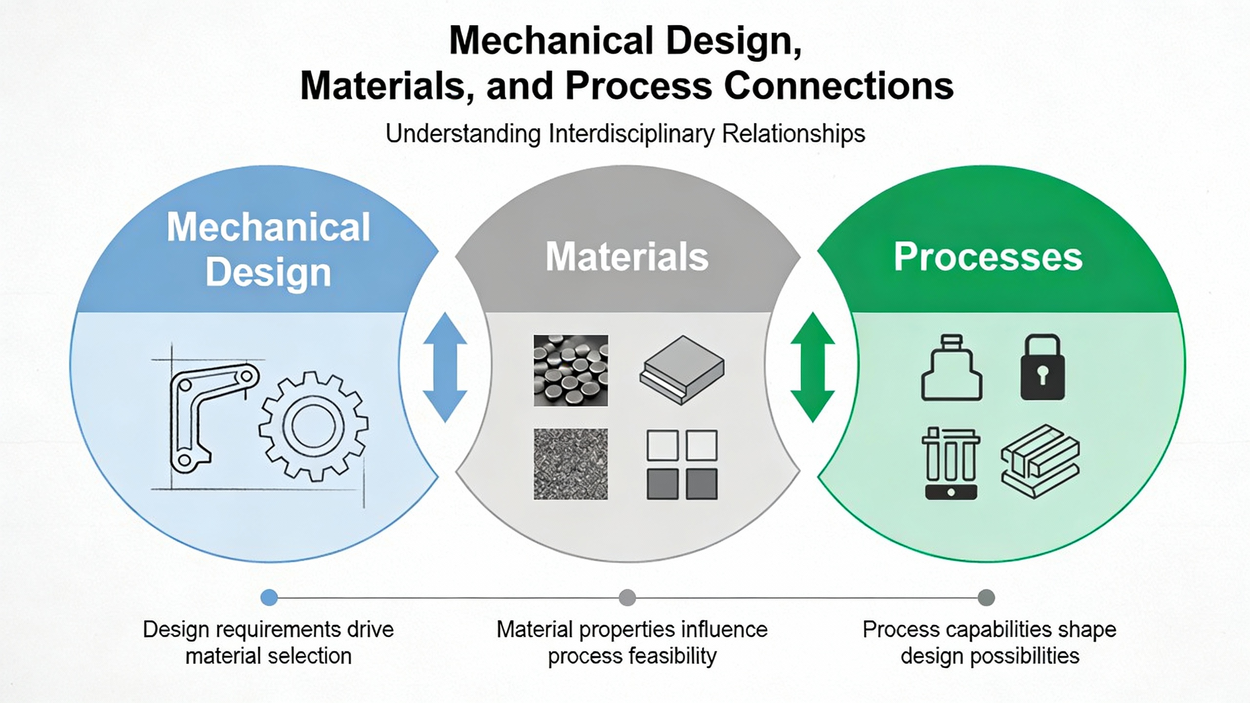
Mechanical Design, Materials, and Process Connections
The mechanical section of a Yokogawa datasheet looks mundane, yet it often determines whether the transmitter survives in a real plant.
A sample EJA110A data sheet referenced in a Scribd document specifies a stainless steel 316 diaphragm and welded cell body with silicone oil fill, mounted in a dieŌĆæcast aluminum housing. Process connections are 1/4 inch NPT female, and the unit is supplied with a twoŌĆæinch pipe mounting bracket. The ingress protection rating is IP67, indicating a dustŌĆætight enclosure that can survive temporary immersion, which is appropriate for cement plants and similar harsh environments cited in that document.
Ye┼¤il Grup EnerjiŌĆÖs guide extends this picture by listing IP66 and IP67 as standard and IP68 as optional protection classes across Yokogawa ranges, with process connections available in NPT, DIN or ISO threaded types, and flanged adapters. Wetted parts are typically stainless steel, with optional alloys like Hastelloy and Monel where aggressive media demand it. BCST GroupŌĆÖs material guidance lines up with this: 316 stainless suits water, steam, oil, and mild chemicals; Hastelloy CŌĆæ276 is preferred for aggressive acids and sour gas; Tantalum and Monel have their own niches in specific corrosive services.
As a simple example, suppose you are measuring differential pressure across a plate heat exchanger carrying treated cooling water in a data center chiller plant. Stainless steel 316 wetted parts on an EJA110E are usually adequate. If instead you are monitoring differential pressure in a scrubber loop with high chloride content, the same datasheet allows you to select a Hastelloy wettedŌĆæpart option to avoid pitting and stress corrosion. The core transmitter electronics and DPharp sensor do not change, but the mechanical code in the model number and its implications for corrosion resistance are what keep you from discovering a leak above critical electrical gear.
YokogawaŌĆÖs EJA110E documentation also highlights rugged construction elements such as a fourŌĆæbolt pressureŌĆæretaining design, a TeflonŌĆæcoated stainless steel 316L flange gasket, and a dual seal certified to ANSI or ISA 12.27.01. Combined with overŌĆærange protection of at least 130 percent of working pressure on the EJA110A sample, these measures allow the transmitter to ride through manifold sequencing errors or process upsets, then return to operation within its published specifications. For plants that see frequent startups and load swings, that robustness is as important as the nominal accuracy.
Electrical, Communication, and Diagnostics
On the electrical side, BCST GroupŌĆÖs overview reminds us that almost all process pressure transmitters still rely on the 4ŌĆō20 mA current loop standard, where 4 mA corresponds to zero percent of calibrated range, 20 mA corresponds to 100 percent, and 0 mA denotes a fault such as power loss or a broken loop. The EJA110A sample sheet confirms a twoŌĆæwire, loopŌĆæpowered 4ŌĆō20 mA output with external zero and span adjustment, powered by 24 VDC and capable of driving up to 600 ohms at that voltage.
Yokogawa builds digital communication on top of that loop. The EJA110A described in the Scribd data sheet and ToprefineŌĆÖs overview is a HART smart transmitter, meaning it superimposes a digital signal on the 4ŌĆō20 mA analog loop. Ye┼¤il Grup Enerji and YokogawaŌĆÖs own TCO article add that other models support BRAIN, Foundation Fieldbus, and Profibus PA, as well as lowŌĆæpower 1ŌĆō5 V DC with HART.
The Yokogawa InTech article on pressure and temperature best practices, together with SMARŌĆÖs intelligentŌĆætransmitter discussion, make several important points about what this actually buys you. First, open communication standards such as HART and FDT enable a mix of devices from multiple suppliers to coexist on the same plant network with minimal translation. Second, stranded diagnostics in existing instruments can often be unlocked simply by enabling a native protocol license, installing an FDTŌĆæbased software plugŌĆæin, or adding a gateway or multiplexer. Third, standards like NAMUR NE107, supported by many modern Yokogawa devices, categorize diagnostic alerts into clear classes such as check function, maintenance required, out of specification, and failure, which helps avoid data overload.
YokogawaŌĆÖs FieldMate software and FieldMate handŌĆæheld communicator sit on top of these protocols, providing configuration and asset management tools. The EJA110E material notes that Local Parameter Setting allows adjustment of several key parameters at the device without a communicator at all, which can be handy when you are in a substation or plant area where carrying extra tools is a burden.
From a powerŌĆæsystem reliability perspective, the key practical point is that diagnostics and communication options on the datasheet are not just convenience features. They decide whether you can move from timeŌĆæbased maintenance to conditionŌĆæbased or predictive maintenance, as the InTech article describes, by monitoring sensor drift, impulse line health, or unusual pressure signatures that may indicate pump or valve problems before they translate into trips or power disruptions.
A compact table can help relate output options to use cases.
| Output / protocol | Typical Yokogawa support | Practical use |
| 4ŌĆō20 mA with HART | EJA/EJX ranges, including EJA110A/EJA110E | Standard control loops with rich diagnostics |
| 4ŌĆō20 mA with BRAIN | Many Yokogawa legacy and current models | Installed base compatibility |
| LowŌĆæpower 1ŌĆō5 V with HART | Selected Yokogawa models | Solar or remote, powerŌĆælimited installations |
| FOUNDATION Fieldbus / Profibus | DPharpŌĆæbased advanced transmitters | Full digital integration and advanced diagnostics |
When you scan a datasheet, verifying that the output signal and protocol match your PLC, DCS, or safety system is just as important as checking the range and accuracy.

Safety, Environmental Ratings, and Approvals
Ye┼¤il Grup EnerjiŌĆÖs guide notes that Yokogawa pressure transmitters carry safety certifications up to SIL2 for single transmitters and SIL3 when used in redundant architectures. YokogawaŌĆÖs own TCO material confirms that their transmitters are designed and thirdŌĆæparty certified to IEC 61508 and IEC 61511 by organizations like Exida and T├£V Rheinland, and that the same models can serve in both process control and safety instrumented functions.
SMARŌĆÖs safety commentary adds an important nuance. SafetyŌĆæcertified transmitters for Safety Instrumented Systems are optimized for predictable failure modes and may impose restrictions such as write protection, disabled local adjustments, and blocked configuration changes during normal operation. That means you should not automatically specify the most expensive SILŌĆærated Yokogawa device for every ordinary control loop. Instead, you should use the datasheet and safety manual to decide where those features are justified and where a standard DPharp transmitter already provides more than enough reliability.
Environmental ratings also require careful reading. Ye┼¤il Grup Enerji lists typical operating temperature ranges from about minus 40 up to roughly 185 degrees Fahrenheit, depending on model, and ingress protection ratings of IP66 or IP67 with optional IP68. The EJA110A sample sheet specifies sensor operating temperatures from about minus 40 up to roughly 219 degrees Fahrenheit and electronics from about minus 40 to roughly 185 degrees Fahrenheit. For a realŌĆæworld example, in a combinedŌĆæcycle plant where transmitters sit near hot HRSG ductwork, those upper limits matter; you may need to mount the transmitter away from the hottest areas and use impulse lines or remote seals, which Yokogawa offers in flangeŌĆæmounted and diaphragmŌĆæseal variants described by Toprefine.
IP ratings, as BCST Group explains, encode dust and water resistance. IP66 signifies dust tight and strong water jet resistance; IP67 adds temporary immersion; IP68 covers sustained immersion to a specified depth. If you are mounting transmitters in a washŌĆædown area or on outdoor pipe racks where they may be submerged during flooding, the difference between IP67 and IP68 on the datasheet is a practical riskŌĆæmanagement consideration.
Finally, YokogawaŌĆÖs TCO material lists a broad portfolio of hazardousŌĆæarea approvals such as FM, CSA, ATEX, IECEx, INMETRO, and others. SMAR and BCST Group both emphasize that matching the approval type and protection concept, such as intrinsic safety or explosionŌĆæproof, to your area classification is nonŌĆænegotiable for safe operation. The model code and certificate references on the datasheet are what your safety team and inspectors will look at.

Using the Datasheet to Select the Right Yokogawa Transmitter
SMARŌĆÖs selection guidance, BCST GroupŌĆÖs specification tutorial, and an EngŌĆæTips engineering discussion converge on a simple truth: even with a strong brand, not every transmitter is the right tool for every job. The datasheet is how you make disciplined choices.
First, you choose the measurement type. The Yokogawa ŌĆ£10 QuestionsŌĆØ interview explains that gauge pressure is appropriate when you care about pressure relative to atmosphere, absolute pressure when atmospheric changes would otherwise distort the measurement, and differential pressure when the pressure difference between two points is the actual variable of interest, such as flow through a restriction or liquid level based on hydrostatic head. ToprefineŌĆÖs model overview clarifies which Yokogawa EJA and EJX models map to each: EJA110A or EJA110E for differential; EJA310A for absolute; EJA430E or EJA510E for gauge, and so on.
Second, you determine the required range and turndown. SMAR defines rangeability as the ratio of upper range limit to minimum calibrated span. BCST Group notes that a high turndown ratio offers flexibility but may degrade accuracy at extreme turndown. If your process normally operates between 50 and 150 psi differential, you might select a transmitter with a 0ŌĆō250 psi upper range limit and calibrate it accordingly, rather than using a 0ŌĆō1000 psi device even if the latter can technically be turned down. The datasheet gives you both upper range limit and minimum span so you can do this tradeŌĆæoff explicitly rather than guessing.
Third, you match wetted materials and process connections. BCSTŌĆÖs materials guidance and Ye┼¤il Grup EnerjiŌĆÖs listing of stainless, Hastelloy, and Monel options help you avoid corrosion and incompatible seals. ToprefineŌĆÖs examples indicate that diaphragmŌĆæsealed or flangeŌĆæmounted EJA variants such as EJA118E or EJA210E are recommended for highŌĆætemperature, viscous, crystallizing, or sedimentŌĆæladen media. If you are monitoring differential pressure across a slurry line feeding a scrubber that protects a turbineŌĆÖs exhaust stack, using a standard directŌĆæmount transmitter would be asking for plugging and premature failure; the datasheet for a diaphragmŌĆæseal model will spell out the maximum temperature and material compatibility for a seal that can survive that service.
Fourth, you consider communication protocol, diagnostics, and integration with your control and asset management systems, as discussed earlier. SMAR and YokogawaŌĆÖs InTech article both advocate selecting intelligent transmitters with open protocols where longŌĆæterm maintenance and performance justify it, and reserving simpler models for nonŌĆæcritical or costŌĆæsensitive services.
As an example, imagine you are qualifying transmitters for a new power plant deaerator level measurement. A Toprefine application note identifies EJA differential pressure transmitters as standard in such services. You would look at EJA110E and perhaps EJX110A datasheets to compare accuracy, stability, turndown, and response time. You would check whether your DCS prefers Foundation Fieldbus or HART, and whether the plantŌĆÖs safety lifecycle requires SIL2 capability on that loop. You would then select the specific model code that combines DPharp measurement performance, stainless steel wetted parts compatible with feedwater chemistry, the correct process connection type, and the communication protocol your DCS and asset management tools support. That entire reasoning chain is anchored in the datasheets and the associated model code tables.
Calibration and Maintenance: What the Datasheet Does Not Do for You
Datasheets state accuracy and stability under specified conditions; they do not calibrate the device, and they do not guarantee that plant conditions will match the ideal. That is where calibration procedures and intervals matter.
A calibration guide from ZYY Instrument for the Yokogawa EJA310A absolute pressure transmitter outlines a practical process that applies equally well to other EJA and EJX models. Before anything else, you isolate the transmitter from the process, close isolation valves, vent residual pressure, and ensure that the device is at zero or atmospheric pressure. Then you connect a standard pressure source, a multimeter to read the 4ŌĆō20 mA output, and a HART communicator or software interface if available.
Calibration proceeds by applying a series of known pressure points, typically at zero, twentyŌĆæfive, fifty, seventyŌĆæfive, and one hundred percent of the transmitterŌĆÖs fullŌĆæscale range, and recording the corresponding output. You then adjust zero and span in the transmitter so that its output matches the expected values at each point. After adjustment, you repeat the pressure sequence to verify that outputs now fall within the specified accuracy band. Finally, you document all applied pressures, readings, and adjustments in a calibration certificate.
ZYY Instrument recommends calibration intervals of roughly six to twelve months depending on application and environment, which aligns with Slideshare material on calibration best practices that emphasizes understanding accuracy, zero drift, linearity, repeatability, and total probable error. YokogawaŌĆÖs DPharp stability guarantee provides justification to extend those intervals where regulations and risk assessments allow, as their TCO analysis suggests, but the starting point is always a documented calibration that ties actual field behavior back to the datasheet numbers.
Environmental control during calibration also matters. ZYY Instrument notes that temperature, humidity, and ambient pressure variations can influence measurements. SMAR and SensorsOne make the same point: temperature coefficients and thermal hysteresis contribute to total error, and they are not always fully captured by a single roomŌĆætemperature accuracy figure. Performing calibration in a controlled workshop, or at least recording ambient conditions and compensating where possible, is part of turning a static datasheet into reliable field performance.
From a reliabilityŌĆæadvisor viewpoint, I look for alignment between the datasheetŌĆÖs stated longŌĆæterm stability, the plantŌĆÖs calibration policy, and the actual measured drift over time. When those three agree, you can confidently stretch calibration intervals without compromising protection. When they do not, you either picked the wrong transmitter or the process conditions are harsher than the datasheet envelope, and both require action.

Brief FAQ
How much accuracy do I really need from a Yokogawa pressure transmitter?
According to PMC and SMAR, many industrial control loops run comfortably with total errors in the range of about ┬▒0.25 to ┬▒0.5 percent of full scale, while highŌĆæend custody transfer and test applications may require around ┬▒0.05 to ┬▒0.1 percent. Yokogawa DPharp transmitters, as described by Ye┼¤il Grup Enerji, Toprefine, and YokogawaŌĆÖs own literature, offer reference accuracies around ┬▒0.04 percent of reading on some models and about ┬▒0.065 percent of span on devices like the EJA110A, with excellent stability. In most power and process applications, that means you can meet your control and protection requirements with ample margin, as long as you select ranges and turndown appropriately and factor in temperature and longŌĆæterm drift.
How often should a Yokogawa DPharp transmitter be calibrated?
ZYY InstrumentŌĆÖs calibration guide for the EJA310A suggests intervals of six to twelve months depending on application and environment, which mirrors general bestŌĆæpractice discussions in Slideshare material on calibration intervals. YokogawaŌĆÖs own stability claims for DPharp devices, supported by ToprefineŌĆÖs note of 0.1 percent stability over five years and YokogawaŌĆÖs longerŌĆæterm guarantees, provide a technical basis for extending those intervals once you have field data showing minimal drift in your specific service. In safetyŌĆæcritical or regulated applications, you still need to follow the governing standards and safety lifecycle requirements, but the datasheetŌĆÖs stability figures allow you to justify longer intervals compared with less stable technologies.
What is the practical difference between an EJA110A and an EJA110E datasheet?
ToprefineŌĆÖs description of the EJA110A and YokogawaŌĆÖs EJA110E product page show that both are differential pressure transmitters based on DPharp technology with similar fundamental accuracy. The EJA110A data sheet emphasizes HART communication, 4ŌĆō20 mA output, stainless steel construction, overŌĆærange protection, and IP67 environmental protection. The EJA110E documentation adds features such as enhanced diagnostics with BackŌĆæcheck Technology, a rugged fourŌĆæbolt design, a TeflonŌĆæcoated 316L flange gasket, dual seals, more explicit safety certifications, and modern assetŌĆæmanagement integration options via FieldMate and advanced local indication. When I compare the two, I treat the EJA110E as an evolution that maintains the core measurement performance of the A series while adding more robust diagnostics, safety, and maintenance tools.
Closing Perspective from a Power Reliability Lens
For those of us responsible for industrial and commercial power systems, a Yokogawa pressure transmitter datasheet is not just a catalog page; it is a risk and reliability specification. When you read it deeply ŌĆō paying attention to measurement type, range, accuracy and stability, mechanical design, communication, safety approvals, and calibration implications ŌĆō you can engineer pressure loops that quietly protect boilers, fuel systems, cooling circuits, and ultimately your UPS and inverter assets for years at a time. When you skim it, the plant pays later. Treat the datasheet as part of your protection philosophy, and YokogawaŌĆÖs DPharpŌĆæbased transmitters can become some of the most dependable ŌĆ£silent guardiansŌĆØ in your power infrastructure.

References
- https://www.academia.edu/129455856/Computer_based_instrumentation_for_pressure_instrument_using_visual_basic_application
- https://docs.lib.purdue.edu/cgi/viewcontent.cgi?article=1886&context=iracc
- https://test.ntinow.edu/Resources/9tBp3d/1S9026/foxboro_pressure-transmitter__manual.pdf
- https://admisiones.unicah.edu/uploaded-files/9tBp3d/1OK026/foxboro_pressure-transmitter__manual.pdf
- https://www.slideshare.net/slideshow/calibration-intervals-best-practices-in-maintaining-pressure-transmitters/62395840
- https://web-material3.yokogawa.com/GS01C21E01-00EN_028.pdf
- https://automationforum.co/how-to-read-the-data-sheet-of-a-pressure-transmitter/
- https://bcstgroup.com/understanding-pressure-transmitter-specification/
- https://pim-resources.coleparmer.com/data-sheet/fluke-calibration-how-to-evaluate-pressure-measurement-specifications-applications-note.pdf
- https://www.mycelectric.com/assets-images/Yokogawa-EJA-Instruction-Manual-14th-Edition.pdf?srsltid=AfmBOooWGWJAt5LwVGiSz3EfHc0bkxWwuSb4UMZukpl1bFZjhiSCMLyd


 Videos
 News
News Applications


Leave Your Comment