Variable frequency drives sit at a critical junction in modern power systems. They connect your upstream supply infrastructureŌĆöutility service, switchgear, UPS, and backup generationŌĆöto the motor loads that actually move product, air, and water. When a VFD is specified correctly, you gain energy savings, stable processes, and fewer failures. When it is not, you inherit nuisance trips, premature motor damage, and unpleasant surprises during peak production.
As a reliability advisor on industrial and commercial power systems, I look at a VFD datasheet less as a sales document and more as a risk profile. In this article, we will walk through the key VFD parameters and what they really mean for performance, protection, and lifecycle cost, using guidance and data from sources such as Control Engineering, Plant Engineering, Darwin Motion, MB Drive Services, ABB, and US DOEŌĆōaligned best practices.
The focus is on practical decisions. By the end, you should be able to read two competing VFD specifications and explain, with confidence, which one is better suited to your motor, your process, and your power system.
Why VFD Specifications Matter for Power and Reliability
A variable frequency drive, also called an AC drive or inverter, controls the speed and torque of an AC motor by converting fixedŌĆæfrequency input power into variableŌĆæfrequency, variableŌĆævoltage output. Instead of slamming a motor across the line at full speed, you can match motor speed to real load demand. Darwin Motion, Control Engineering, and Plant Engineering all emphasize the same three benefits: energy savings, improved process control, and reduced mechanical stress.
For centrifugal loads such as fans and many pumps, the impact on energy is dramatic. Plant Engineering notes that power demand for these loads falls sharply with speed; at half speed, power draw can be as little as oneŌĆæeighth of fullŌĆæspeed power. E&I Sales describes a rule of thumb that cutting speed by about twenty percent on fans and pumps can trim energy use by roughly fifty percent. Control Engineering reports that HVAC fans and pumps can often save up to fifty percent, conveyors around thirty to forty percent, and centrifugal pumps up to sixty percent when operated intelligently with VFDs. Those are not marginal gains; they are businessŌĆæcase defining numbers.
From a reliability perspective, a VFDŌĆÖs softŌĆæstart capability avoids the inrush currents and torque shocks associated with acrossŌĆætheŌĆæline starts, which according to multiple sources significantly reduces wear on belts, couplings, gearboxes, and even piping in pumped systems. The US DOEŌĆōaligned motor and drive system sourcebooks cited by Reliamag highlight that smoother starting and tighter control extend equipment life and reduce unplanned downtime.
The market has taken note. E&I Sales cites estimates that the global VFD market is already in the tens of billions of dollars, with projections ranging from the lowŌĆæthirtyŌĆæbillion range to over sixtyŌĆæfive billion dollars by the early 2030s. SHCKele reports similar projections around the midŌĆætwentyŌĆæbillion level by the middle of this decade, driven by industrial automation, HVAC optimization, and pairing with highŌĆæefficiency motors. In other words, drives are now a core element of modern power systems, not an exotic accessory.
A simple energy example illustrates why you should care about the specifications rather than just the price. Imagine a fan that would draw 50 hp at full speed if run across the line. If the process only needs half that flow most of the time, a VFD that allows the fan to run around half speed might cut the electrical power toward oneŌĆæeighth of the fullŌĆæspeed value during those periods, based on the centrifugal affinity laws highlighted by PrecisionŌĆæElectronics and Plant Engineering. Over a year of operation, that easily translates to thousands of dollars saved, even before considering reduced maintenance cost.
Those savings only materialize if the drive is correctly matched to the motor and the application. That starts with the most fundamental parameters on every VFD specification.
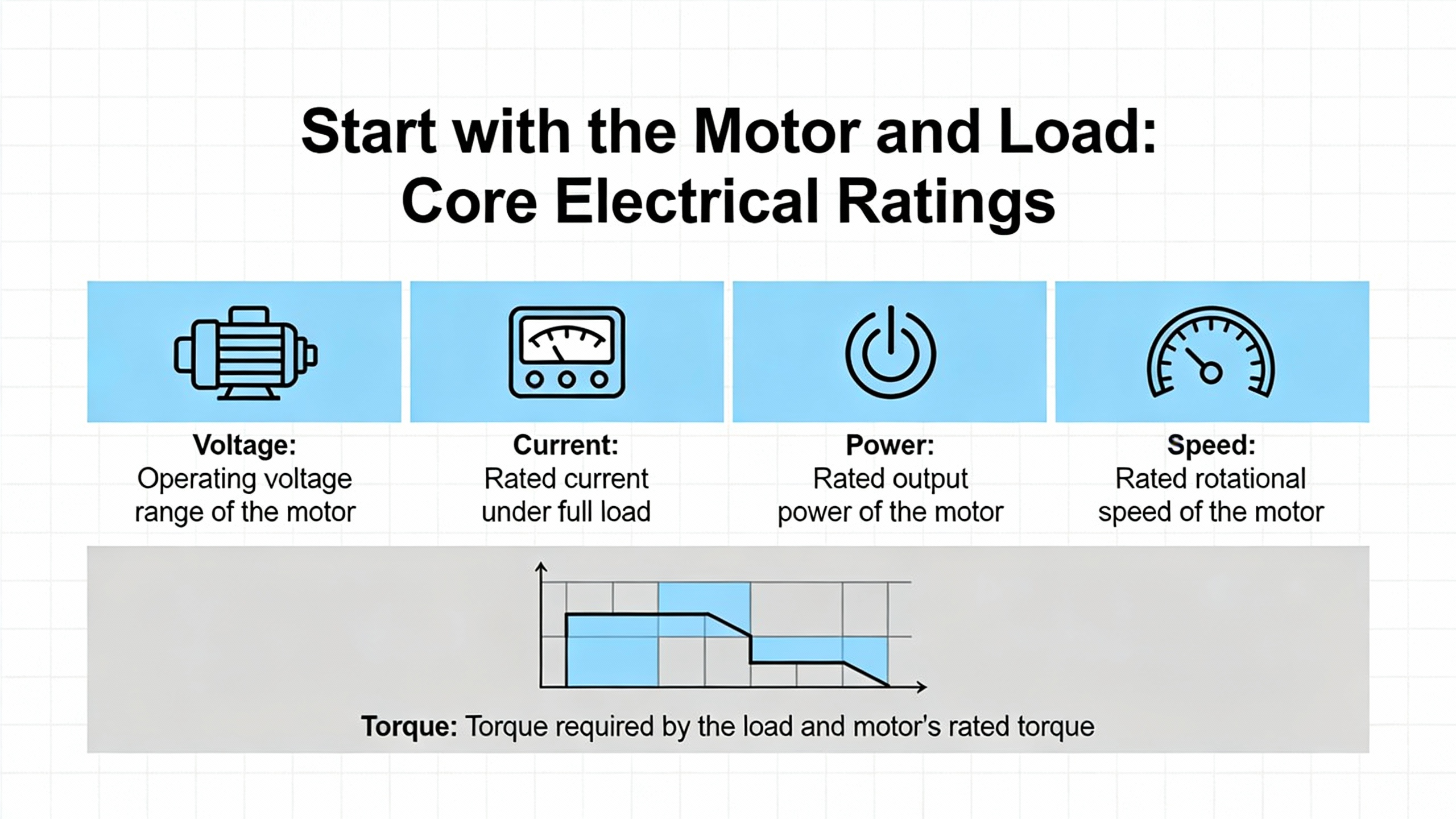
Start with the Motor and Load: Core Electrical Ratings
Every good VFD comparison begins at the motor nameplate. The temptation is to scan for horsepower and choose the cheapest drive with the same hp rating. E&I Sales and Darwin Motion both warn against that shortcut. A VFDŌĆÖs primary job is to manage current, not horsepower, and its continuous and peak current ratings must align with what your motor and load will demand.
Motor nameplate: the nonŌĆænegotiable inputs
When I review a drive spec, I always crossŌĆæcheck it against three critical nameplate values: rated voltage, fullŌĆæload amps, and service factor.
The motorŌĆÖs rated voltage must match the VFDŌĆÖs output rating, and the driveŌĆÖs input voltage must match your supply (for example, 480 V threeŌĆæphase). Darwin Motion stresses that this is simple but nonŌĆænegotiable; mismatches here lead directly to damage or nuisance trips.
FullŌĆæload amps (FLA) is the most important sizing parameter. E&I Sales is explicit that you should size the drive based on the motorŌĆÖs FLA, not its horsepower. Two motors of the same hp but different efficiency, design letter, or manufacturer can have noticeably different FLA. If you size a VFD to a lower FLA than the motorŌĆÖs actual fullŌĆæload current, you are baking in overload alarms and potential drive faults during normal production.
Service factor is another quiet but important line. A motor with a service factor above 1.0, such as 1.15, is designed to carry overload for limited periods. E&I Sales notes that if you intend to actually use that extra thermal margin, the drive must be able to source the corresponding extra current without tripping. That often means choosing a drive frame with higher overload capacity than the bare FLA might suggest.
A practical example helps. Suppose you have two fortyŌĆæhorsepower motors available for a new pump, and your plant standard drive frame is rated just above the FLA of the more efficient motor. If you pick the less efficient motor with higher FLA but keep the same drive, you may see overload trips even though the horsepower looks correct on paper. The correct approach is to size the VFD to the higher FLA or select a higherŌĆærated drive if you plan on future process increases that will push toward the serviceŌĆæfactor region.
Load profile and duty cycle
Once the motor is understood, the drive must be matched to the mechanical load. Darwin MotionŌĆÖs selection guidance and the pumpŌĆæfocused work from Pumps.org divide loads into broad categories that matter for VFD specifications.
VariableŌĆætorque loads, such as centrifugal fans and rotodynamic pumps, require torque that increases with speed. These are relatively ŌĆ£easyŌĆØ loads for VFDs; starting torque requirements are modest, and energy savings from speed reduction are large. A standardŌĆæduty drive, properly sized on FLA, is usually adequate, and simple voltsŌĆæperŌĆæhertz control will often be sufficient.
ConstantŌĆætorque loads, such as positive displacement pumps, extruders, mixers, and many machine tools, demand high torque even at low speeds. Positive displacement pumps, for example, can reach full discharge pressure at relatively low speed, according to Pumps.org. These loads stress the drive differently. They may need higher overload capacity, more robust thermal design, and more advanced control methods to maintain torque at low speed without overheating motor or drive.
Duty cycle matters as well. Darwin Motion and E&I Sales both mention that frequent starts and stops, rapid acceleration and deceleration, and high duty cycles can push a drive toward its thermal and electrical limits. In many drive families there are separate ratings for constantŌĆætorque and variableŌĆætorque duty, each with different allowable overload durations. When comparing specifications, you should look beyond the continuous current rating and examine the allowable overload percentage and time (for example, whether the drive can supply roughly oneŌĆæandŌĆæaŌĆæhalf times rated current for around a minute and perhaps twice rated current for a few seconds, as indicated in ABBŌĆæfocused checklists). These overload capabilities are directly tied to the service factor and starting torque of the connected motor.
A realŌĆæworld illustration: consider a mixer that operates with frequent starts and stops and must hold high torque at low rpm while maintaining product quality. A drive sized just at the motorŌĆÖs FLA with limited overload might look fine at constant speed but could trip repeatedly under real batch operation. Selecting a drive with stronger overload capability and appropriate control mode, discussed next, prevents those operational headaches.
Control Methods and Performance Specifications
Not all VFDs regulate motors in the same way. Under the hood, control algorithms dictate how the drive generates voltage and frequency in response to load and feedback. E&I Sales, Darwin Motion, and an engineering forum discussion on slip and speed reference all distinguish three main control families that appear on datasheets: scalar voltsŌĆæperŌĆæhertz, sensorless vector, and closedŌĆæloop vector control.
From a spec comparison standpoint, the control method affects lowŌĆæspeed torque, speed regulation, dynamic response, and cost. Put differently, it defines how ŌĆ£smartŌĆØ the drive is.
Comparing the main control methods
The following table summarizes the essential differences, distilled from E&I Sales, Pumps.org, and Control Engineering coverage.
| Control method | Key principle | Typical applications | Performance and cost |
| Volts per hertz | Keeps a constant voltageŌĆætoŌĆæfrequency ratio | Fans, centrifugal pumps, simple conveyors | Basic speed control, weaker lowŌĆæspeed torque, lowest cost |
| Sensorless vector | Uses a motor model to control flux and torque | Extruders, mixers, positive displacement pumps, general machinery | Good torque and speed control across a wide range, medium cost |
| ClosedŌĆæloop vector | Adds encoder feedback for precise speed and position | Cranes, hoists, web lines, highŌĆæprecision spindles | Excellent torque even at zero speed, tight speed regulation, highest cost and complexity |
VoltsŌĆæperŌĆæhertz, also called scalar control, is the workhorse. It maintains a fixed voltageŌĆætoŌĆæfrequency ratio so that motor flux and torque stay roughly constant as speed changes. It does not know actual rotor speed and does not directly compensate for slip. An engineering discussion on determining frequency reference notes that, in this mode, motor mechanical speed always lags synchronous speed by a loadŌĆædependent slip that the drive does not correct. For the majority of variableŌĆætorque applications, such as building fans and water pumps, that is acceptable, and the simplicity makes scalar drives robust and economical.
Sensorless vector control is designed for constantŌĆætorque loads that need better regulation. As E&I Sales explains, the drive builds an internal model of the motor and uses voltage and current measurements to estimate rotor speed and torque. It can independently manage magnetizing current and torqueŌĆæproducing current, which gives much stronger torque at low speed without a shaft encoder. The same engineering forum points out that in this mode, the drive internally calculates the slip needed to produce torque and adds it to the commanded speed, essentially closing the loop on speed without physical feedback.
ClosedŌĆæloop vector, sometimes called fieldŌĆæoriented control with encoder feedback, takes performance one step further. An encoder on the motor shaft gives realŌĆætime speed and position data to the drive, which allows precise torque and speed regulation, including at zero speed. E&I Sales and Pumps.org highlight this mode for demanding applications such as cranes, hoists, web handling, and highŌĆæspeed spindles, where even small speed errors can ruin product or create safety risks.
E&I Sales notes that simple voltsŌĆæperŌĆæhertz control is suitable for roughly eighty percent of standard VFD applications. The important specification question is whether your application sits inside that majority or in the remaining slice that truly needs vector control.
Example: choosing control method by application
Consider three scenarios that show how these control specs play out.
For an airŌĆæhandling unit supply fan in an office building, the main goals are energy efficiency, modest speed control accuracy, and reliable operation with minimal tuning. A scalar VFD with good variableŌĆætorque ratings and basic communication will typically meet these needs at the lowest installed cost. Tight lowŌĆæspeed torque is rarely critical because the fan does not spend significant time at nearŌĆæzero speeds under load.
For an industrial mixer that must maintain torque at low speed while keeping product consistency, the situation changes. Sensorless vector control allows the VFD to estimate rotor speed and torque accurately and adjust output to hold speed as viscosity and load change. This leads to more consistent batches and fewer nuisance trips when the product thickens, at a moderate cost premium.
For an overhead crane that must position loads precisely and hold them safely at zero speed, closedŌĆæloop vector control with an encoder becomes important. The encoder feedback helps deliver full torque at zero speed and accurate positioning. Here, the tighter performance specifications justify the extra hardware, complexity, and cost because safety and mechanical stress risk are high.
When comparing datasheets, look not just for the control method labels, but also for claims about speed regulation accuracy, lowŌĆæspeed torque capability, and whether the drive can operate in multiple control modes. That flexibility can be valuable if the same drive family will feed a range of loads in your facility.
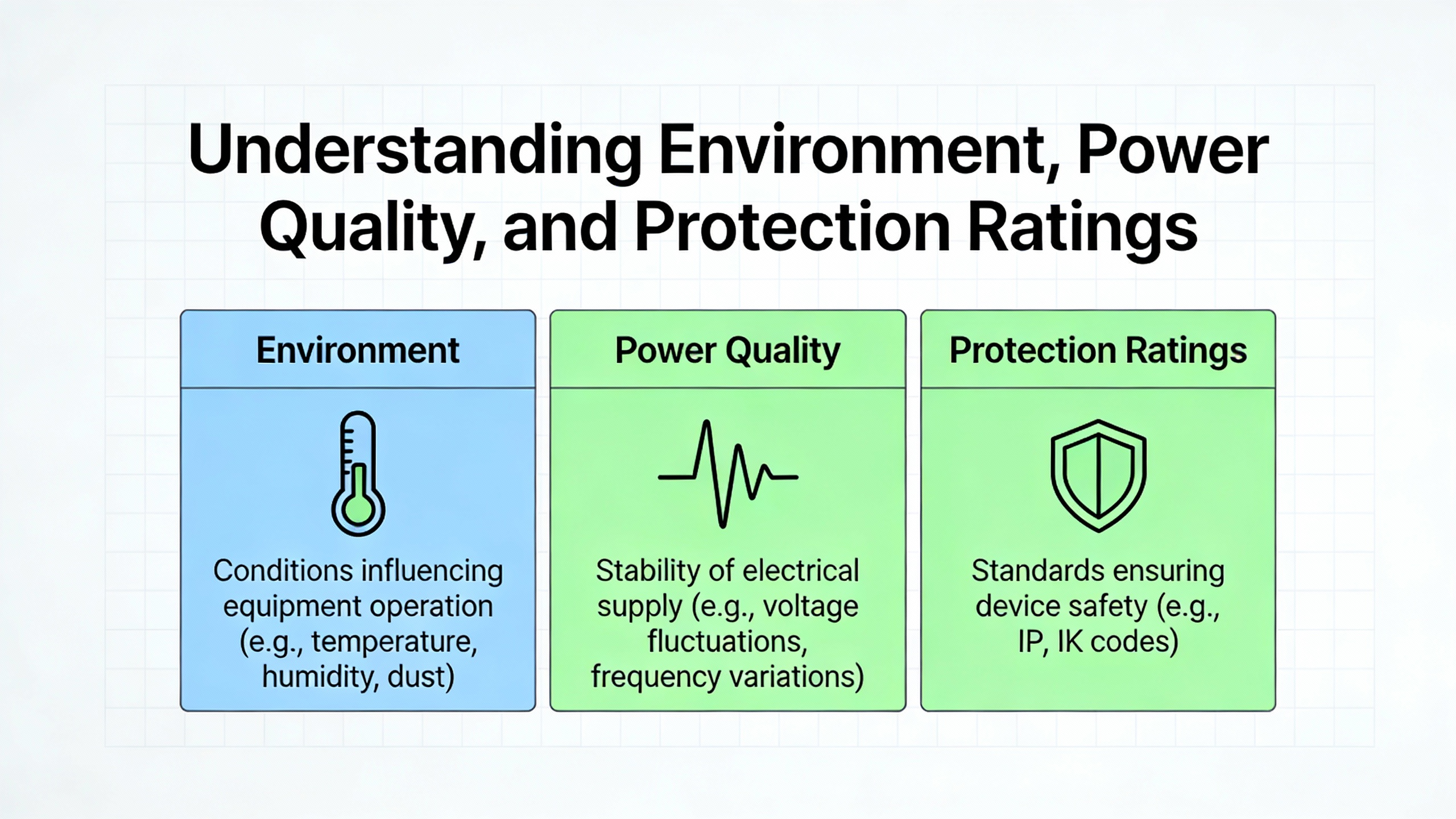
Environment, Power Quality, and Protection Ratings
Specifying electrical ratings and control methods is only half the story. Drives live in real electrical rooms, rooftops, mechanical spaces, and production lines, where dust, temperature, moisture, and power quality issues can quietly kill them long before the semiconductors wear out.
Darwin Motion and SHCKele both stress matching the VFDŌĆÖs environmental and mechanical design to the site. This is where enclosure ratings, cooling requirements, and input power quality specifications on the datasheet become critical.
Enclosure and environmental ratings
Manufacturers often describe enclosures with ingress protection codes such as IP20, IP54, IP65, or IP66. SHCKele notes that lower ratings, like IP20, are suitable for clean electrical rooms, while higher ratings like IP54 and IP65 are intended for dusty or damp environments and outdoor or washŌĆædown areas.
ReliamagŌĆÖs guidance on motor and VFD inspection indicates that temperature is a leading enemy of both electrical insulation and lubricants. For VFDs, they recommend deŌĆæenergized annual cleaning, vacuuming, and tightening of power connections, along with following OEM maintenance schedules, especially on mediumŌĆævoltage drives. If a drive is installed in a hot, dirty mechanical room with poor airflow, an openŌĆætype enclosure with minimal dust protection is a recipe for overheating and contamination. In those cases, when comparing drives, favor models with higher ingress protection, suitable operating temperature ranges, and enough internal or external cooling to keep electronics in their comfort zone.
A practical scenario illustrates why this matters. Suppose you are adding VFDs for cooling tower fans on a rooftop. The drives will see moisture, temperature swings, and possibly chemical exposure from treatment chemicals. A compact IP20ŌĆærated unit intended for a clean indoor panel, even if electrically adequate, is likely to fail early. An IP54 or IP65 design mounted in a weatherŌĆærated enclosure, with maintenance access for annual cleaning, aligns better with the environment and the reliability targets.
Power quality, harmonics, and protection components
VFDs impact the upstream power system because the rectifier front end draws current in pulses. Control Engineering and Plant Engineering both point out that this nonŌĆælinear draw can introduce harmonics, reduce power factor, and create lineŌĆæside voltage distortion if not mitigated. Darwin Motion recommends planning for harmonic management, whether through filters or higherŌĆæperformance input designs, to meet plant power quality requirements.
Plant Engineering describes input line reactors as a best practice. Installing an input reactor between the supply and the drive limits inrush currents from transient line events, such as utility capacitor switching, and reduces DC bus overvoltage trips. These reactors also help smooth the input current waveform, lowering harmonic voltage distortion on the upstream bus. When comparing VFD specifications, note whether line reactors are integrated, required, or offered as accessories, and whether the manufacturer provides harmonic performance data for typical setups.
On the output side, fast switching in the inverter can stress motor insulation and bearings. Plant Engineering explains that long motor leadsŌĆöon the order of a hundred feet and beyondŌĆöcan cause voltage reflections that double the apparent voltage at the motor terminals, accelerating insulation breakdown. For these installations, they recommend output line reactors, dv/dt filters, sine filters, or snubber circuits at the motor, depending on cable length. Pumps.org further notes that PWM switching can induce shaft voltages that discharge through bearings, causing pitting and fluting; shaft grounding rings or insulated bearings are common mitigations.
From a reliability advisorŌĆÖs perspective, this means that whenever you compare drive specs for an application with long cable runs or inverterŌĆæduty motor concerns, you should view the drive and its recommended line and loadŌĆæside accessories as a package. A slightly cheaper drive that requires extensive external filtering to survive a longŌĆælead installation may be less attractive than a model designed with more robust output capabilities and clear guidance on cableŌĆælength limits.
A concrete example: consider a well pump installation with the drive in a building and the motor several hundred feet away. Plant Engineering suggests that beyond roughly five hundred feet of cable, basic output reactors may not be adequate, and dv/dt or sine filters become appropriate. For this application, a drive family that offers tested filter combinations and clear motorŌĆæterminal voltage limits in its documentation will be easier to deploy and maintain than one that leaves those details vague.
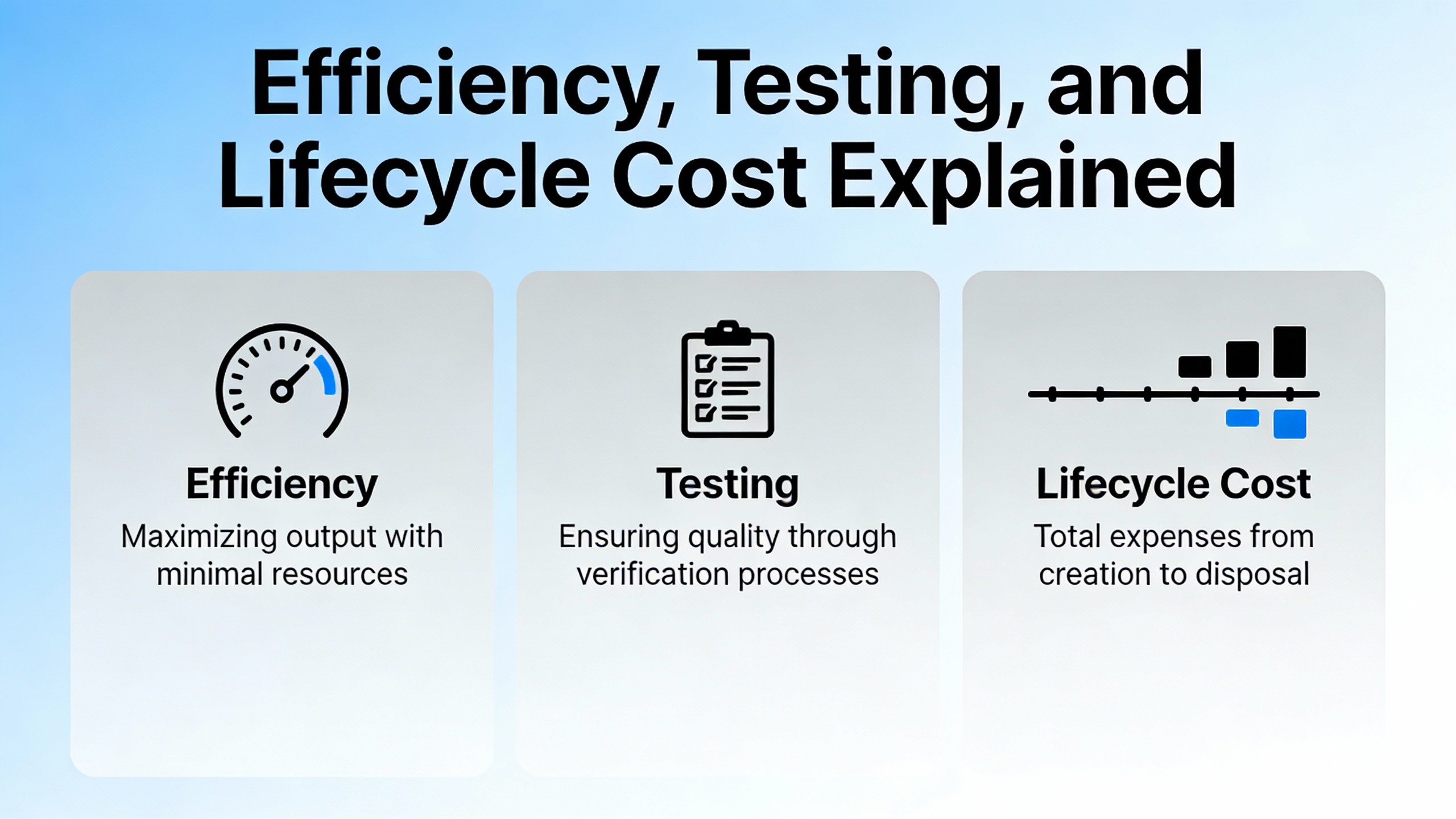
Efficiency, Testing, and Lifecycle Cost
Drive efficiency specifications tend to be a small footnote on many datasheets, but in a powerŌĆæintensive facility they can have real financial impact. Darwin Motion and PrecisionŌĆæElectronics both emphasize that total cost of ownership, not just purchase price, should drive selection. That total includes energy consumption, maintenance and downtime, and the cost of eventual replacement.
Understanding efficiency ratings and measurement
MB Drive Services discusses how international standards such as IEC 60146ŌĆæ1ŌĆæ1 and IEC 61800ŌĆæ4 define converter efficiency measurement. They note that efficiency can be established by measuring AC input and DC output power, by carefully calculating internal losses, or by directly measuring those losses. The standards require that all apparatus used in determining efficiency be documented and that measurement tolerance on losses be tight, on the order of less than about twoŌĆæthousandths of the output power.
MB Drive Services gives a concrete example. If a VFD has approximately 98.5 percent efficiency, its losses are about 1.5 percent of output power. If your instruments have a ten percent tolerance on measured losses, that equates to roughly 0.15 percent with respect to output power, which is still within the recommended limit of 0.2 percent. IEC 61800ŌĆæ4 concludes that direct loss measurement methods tend to be more accurate for highly efficient systems and are preferable for drives with high efficiency values.
From a spec comparison standpoint, this tells you two things. First, if one manufacturer publishes detailed efficiency data over load and speed, backed by recognized standards, and another simply claims ŌĆ£high efficiencyŌĆØ with no context, the former deserves more credibility. Second, when energy consumption is a significant part of your operating budget, even small differences in efficiency matter.
Consider an example using the centrifugal load savings previously discussed. If a fan systemŌĆÖs energy use can be cut by fifty percent using a VFD, as reported by Control Engineering for many HVAC applications, then the absolute energy passing through the drive over its life is enormous. A difference of one percentage point in drive efficiency, over years of operation, can translate to substantial additional waste heat and cost. PrecisionŌĆæElectronics notes that VFD projects in fans, pumps, and conveyors often achieve simple payback in roughly one to three years, largely due to these savings. Drives that run cooler and more efficiently also reduce strain on cooling systems and improve component longevity.
Testing, commissioning, and periodic verification
Darwin MotionŌĆÖs overview of VFD testing applications and FlukeŌĆÖs motor drive analyzer guidance both stress that formal testing is not just a lab exercise. Functional testing ensures that startŌĆæstop behavior, speed control, and fault detection match expectations. Load testing checks whether torque and speed are maintained under real loads. Harmonic analysis reveals how the drive affects power quality. Transient response and safety testing verify that the system behaves properly during disturbances and emergencies.
FlukeŌĆÖs guidance shows how modern analyzers simplify these tasks with guided workflows and automated calculations, making it practical to perform these tests during commissioning and troubleshooting. Zero InstrumentŌĆÖs best practices for testing VFDs with a multimeter add lowŌĆætech but essential checks, such as verifying DC bus voltage levels, phase balance, and diode or IGBT health in unpowered drives.
From a specification perspective, you want drives that expose the right data and interfaces to support such testing. Parameters such as builtŌĆæin diagnostics, accessible DC bus terminals for measurement, clear fault code descriptions, and communication options to log operating data all influence how easily your maintenance team can verify and sustain efficiency over time.
A straightforward example: after commissioning a large fan VFD, performing a set of baseline tests to capture input power, output power, DC bus voltage, and harmonic levels at a few key load points creates a performance fingerprint. Years later, you can repeat those tests. If efficiency has drifted or harmonics have increased, you have hard data to justify maintenance or investigation. Drives with better diagnostic capabilities make this process quicker and provide higher confidence in the results.
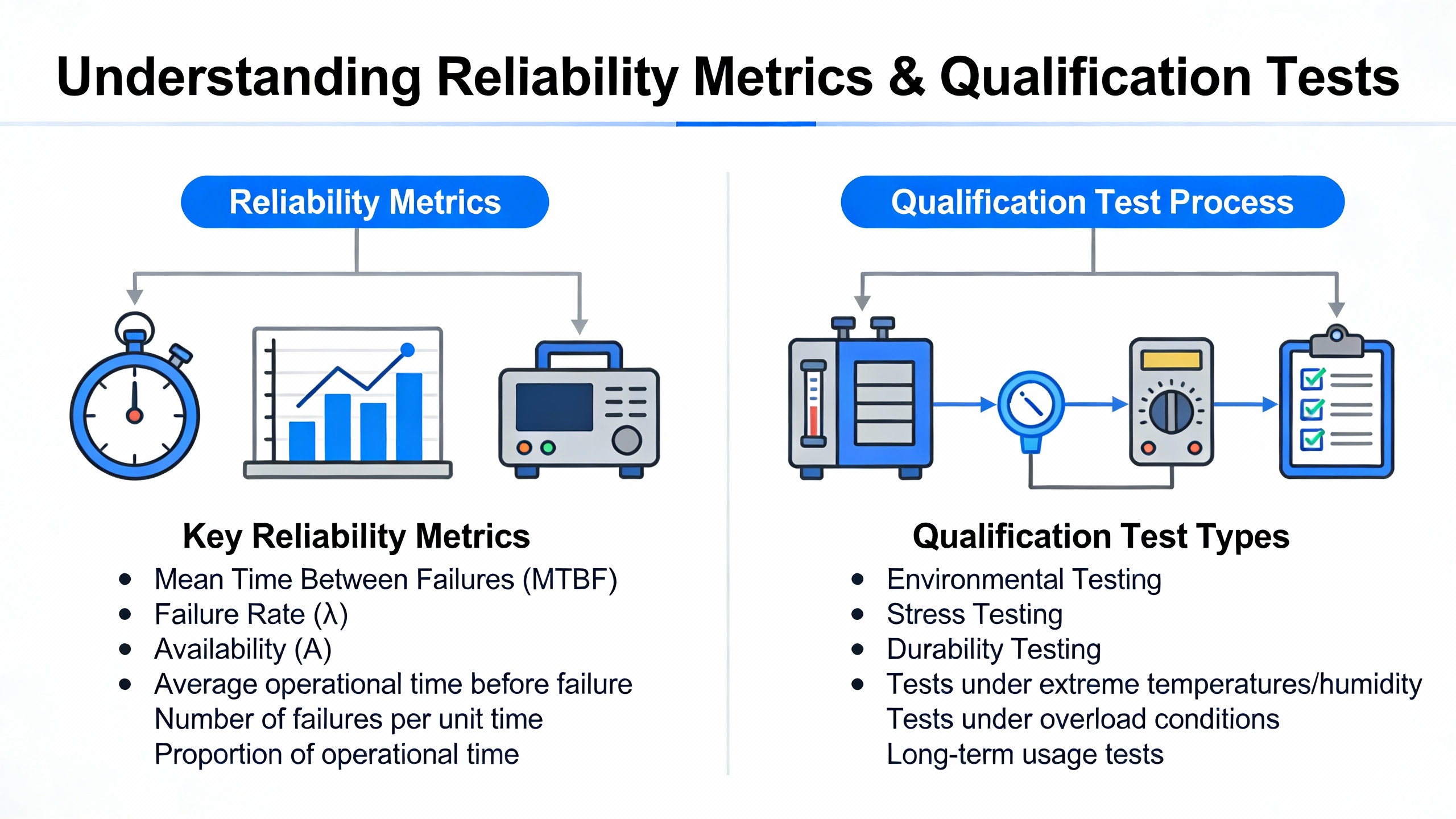
Reliability Metrics and Qualification Tests
Energy efficiency is one side of the lifecycle cost equation; reliability is the other. A highly efficient drive that fails unexpectedly during peak season is not a bargain. IllinoisŌĆæbased guidance on VFD reliability measurement and ABBŌĆÖs work on reliability testing outline how serious manufacturers and asset managers quantify reliability.
MTBF and what it really tells you
Mean time between failures, or MTBF, is a common metric on datasheets. Illinois Electric explains MTBF as the average operational time between inherent failures, derived from historical data and statistical analysis. Higher MTBF implies longer expected operational life and better reliability, at least in theory.
However, MTBF figures are only as meaningful as the assumptions behind them. They often depend on operating temperature, load, environmental conditions, and maintenance levels. If two VFDs list very different MTBF values, you should ask how those numbers were derived and whether they reflect your reality. Drives intended for harsh environments should have environmental testing and field data that support their claims.
Accelerated life testing, RDT, and field data
ABB describes two complementary approaches: Reliability Demonstration Testing (RDT) and Accelerated Life Testing (ALT). RDT, performed during development, exposes a limited number of drivesŌĆöoften in the range of several to a couple of dozen unitsŌĆöto stresses that simulate their lifetime, typically dominated by temperature cycling. If all units survive the test profile, the product can be released with confidence that it meets a defined life target.
ALT, in contrast, deliberately runs devices to failure under elevated stresses to uncover failure modes, refine material models, and improve lifetime predictions. ABB notes that larger samples, potentially up to several dozen drives, may be required for ALT, and tests can simulate roughly a decade of operation in a few months using accelerated conditions such as higher temperatures.
Illinois Electric emphasizes that robust reliability assessment also includes componentŌĆælevel analysis of capacitors, semiconductors, and cooling systems; environmental testing for temperature, humidity, dust, and vibration; and field data collection from real installations. That field data, combined with realŌĆætime monitoring and predictive maintenance techniques, helps detect emerging issues early and refine reliability estimates.
When comparing VFD specifications, ask whether the manufacturer can share summaries of their environmental and life testing and whether their MTBF values are backed by such programs. A drive series that has undergone structured ALT and RDT, supplemented with field data from similar applications, is far more likely to deliver the uptime your UPS, generators, and production lines depend on.
Maintenance practices that protect the investment
ReliamagŌĆÖs best practices for motor and VFD inspection highlight practical steps that tie directly to reliability outcomes. These include having clear repair standards aligned with ANSI/EASA AR100 or IEEE 1068, structured decisions on repair versus replacement based on US DOE Office of Industrial Technologies guidance, formal lubrication programs for motors, regular cleaning of cooling passages and filters, and careful management of spares.
For VFDs, they recommend deŌĆæenergized cleaning and tightening of power connections at least annually, adherence to OEM maintenance schedules (especially for mediumŌĆævoltage drives), and targeted periodic diagnostics. Combining these practices with the reliabilityŌĆæcentered testing described by ABB and Illinois Electric turns the raw reliability potential in the driveŌĆÖs design into real uptime in your plant.
Putting It Together: Comparing VFD Datasheets for Real Applications
With all these parameters in mind, how do you practically compare two VFD specifications for a real project? The answer is to anchor the comparison in your motor, your load, your environment, and your risk tolerance, then read the datasheets through that lens.
The table below outlines how different parameters should be prioritized for three common load types, based on insights from Darwin Motion, Plant Engineering, Pumps.org, Control Engineering, and the reliability sources described earlier.
| Application type | HighestŌĆæpriority parameters | Typical control and protection choices |
| HVAC fans and centrifugal pumps | Motor FLA, variableŌĆætorque rating, efficiency, harmonic impact | Scalar voltsŌĆæperŌĆæhertz; input line reactor; basic output reactor where leads are long |
| ConstantŌĆætorque mixers and extruders | Overload capacity, lowŌĆæspeed torque, cooling, enclosure | Sensorless vector control; higherŌĆæduty rating; robust cooling and IP54 or better where the environment is harsh |
| Cranes, hoists, webŌĆæhandling lines | ClosedŌĆæloop vector capability, encoder interface, braking, safety functions | ClosedŌĆæloop vector with encoder; attention to braking choppers and resistors; strong diagnostics and communication |
A short worked scenario shows how this plays out in practice.
Imagine you are equipping a new process line with a supply fan, a jacketed mixer, and a small overhead hoist.
For the supply fan, the motor is a standard threeŌĆæphase induction motor on a roofŌĆæmounted fan. The load is variableŌĆætorque with long run hours at partial load. You start by selecting a drive with continuous current comfortably above the motorŌĆÖs FLA and a strong variableŌĆætorque rating. Because Plant Engineering and Control Engineering both show that energy savings can reach fifty percent or more in this type of application, you pay attention to efficiency data and possibly favor a drive series with higher efficiency ratings. The roof environment pushes you toward a drive with an appropriate IP rating and clear guidance on outdoor or panelŌĆæmounted use. If the cable run to the motor is long, you incorporate the recommended output filtering to protect the motor insulation.
For the mixer, you know from Pumps.org and E&I Sales that positive displacementŌĆælike torque behavior at low speed will stress both the motor and the drive. You choose a drive in sensorless vector mode, with overload capability aligned to your process peaks and motor service factor, and you check that its cooling and enclosure ratings suit the washŌĆædown or chemical environment. The control specifications for lowŌĆæspeed torque and speed regulation become important for maintaining product quality.
For the hoist, safety and precise positioning dominate. ClosedŌĆæloop vector control with an encoder interface is a must, and you pay close attention to braking capabilities, faultŌĆæhandling behavior, and diagnostic features. Here, you might also ask the supplier about the driveŌĆÖs reliability testing and MTBF data, given the risk associated with failure during lifting operations.
In all three cases, you are reading the same categories of specificationsŌĆöcurrent ratings, control methods, enclosure, efficiency, and reliabilityŌĆöbut weighting them differently based on application need.
Short FAQ on VFD Specifications
How much margin should I include when sizing a VFD?
Reliable sources such as E&I Sales and Darwin Motion agree that drives should be sized at least to the motorŌĆÖs fullŌĆæload amps, not just horsepower, and that additional margin is justified when the application routinely uses motor service factor or has heavy overloads. Instead of a fixed percentage rule, focus on the driveŌĆÖs published overload ratings and ensure they cover your worstŌĆæcase operating scenarios, including starts, acceleration, and occasional process upsets.
Is it worth paying extra for vector control on simple fans and pumps?
In most cases, no. E&I Sales notes that simple voltsŌĆæperŌĆæhertz control is appropriate for the majority of standard VFD applications, especially variableŌĆætorque loads like HVAC fans and many centrifugal pumps. Vector control shines in constantŌĆætorque, lowŌĆæspeed, or precision applications such as extruders, mixers, and hoists. Paying for vector capability on a basic ventilation fan rarely yields tangible benefit unless you anticipate future upgrades that will demand tighter control.
Do higherŌĆæefficiency VFDs really pay off in practice?
Plant Engineering, Control Engineering, and PrecisionŌĆæElectronics all show that the bulk of the energy savings in a VFD project come from matching motor speed to load, especially for centrifugal loads. However, MB Drive Services reminds us that drive efficiency matters too, and that highŌĆæefficiency drives are worth specifying on large or heavily loaded applications. Combined with the fact that more efficient drives run cooler, which enhances reliability, the modest premium for higherŌĆæefficiency units often pays back over the life of the equipment, especially where operating hours and power costs are high.
A VFD is not just a speed controller; it is a critical powerŌĆæconversion asset that sits between your supply infrastructure and your most important rotating machines. When you evaluate VFD parameters through the lens of motor compatibility, load behavior, environment, efficiency, and reliability testing, you move beyond catalog shopping and into engineering. That is where power systems become not only efficient but also robust, predictable, and ready for the demands your operation will place on them.
References
- https://docs.nrel.gov/docs/fy17osti/68574.pdf
- https://www.pumps.org/pump-pros-know-variable-frequency-drives/
- https://www.ahrinet.org/system/files/2023-06/AHRI_Standard_1211_SI_2019.pdf
- https://www.hars-vfd.com/how-to-select-the-right-variable-frequency-drive-for-your-application.html
- https://www.controleng.com/variable-frequency-drive-advice-best-practices-for-engineers/
- https://darwinmotion.com/blogs/7-considerations-for-selecting-a-variable-frequency-drive
- https://www.illinoiselectric.com/single-post/how-is-variable-frequency-drive-reliability-measured
- https://mb-drive-services.com/how-to-measure-vfd-efficiency/
- https://www.plantengineering.com/vfd-efficiency-three-best-practices/
- https://www.realpars.com/blog/variable-frequency-drive


 Videos
 News
News Applications


Leave Your Comment